Table of Contents
Residential Power Distribution
A power distribution system is essential for delivering electrical power throughout a building. These systems are crucial in every residential, commercial, and industrial setting. They ensure that electrical energy is efficiently and safely distributed to various building parts, providing the necessary power for lighting, appliances, and machinery.
Most of us are familiar with the power distribution system found in the average home. Power, purchased from a utility company, enters the house through a meter that records the electrical energy used.
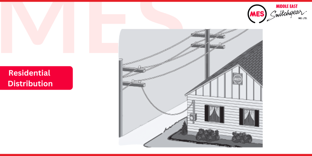
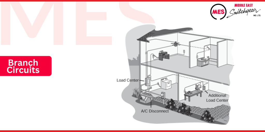
The incoming power typically flows into a load center, which offers circuit control and overcurrent protection. From the load center, the power is distributed to various branch circuits that supply lighting, appliances, and electrical outlets.
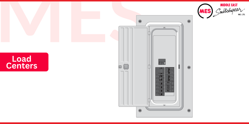
Load Centers
A load center is an industry term for the type of panelboards used in residential and light commercial applications. According to the National Electrical Code®, there is no distinction between a panelboard and a load center; therefore, the rules and definitions that apply to panelboards also apply to load centers.
Definition
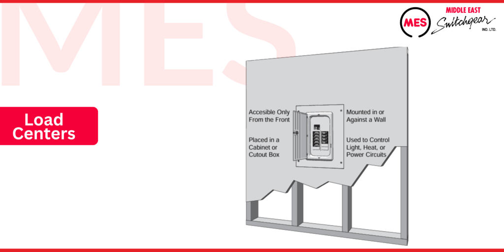
A panelboard is an enclosure designed for overcurrent protection devices and includes the busses and connections that deliver power to these devices and their associated circuits. According to the National Electrical Code® (NEC®), panelboards, which include load centers, must adhere to specific standards:
- Used to control light, heat, or power circuits.
- Placed in a cabinet or cutout box.
- Mounted in or against a wall.
- Accessible only from the front.
Key Features for Panelboards
Panelboards are essential for managing and protecting electrical circuits. They house critical components such as circuit breakers and fuses, safeguarding your electrical system from overloads and short circuits. By understanding their role and placement requirements, you can ensure safe and efficient power distribution in any building.
Load Center Construction
Load centers are constructed from the following three parts: enclosure, interior, and trim.
Enclosure
The enclosure of a load center is typically made from cold-rolled steel for indoor use or galvanized steel for outdoor applications. Along with the trim, the enclosure is designed to ensure both component and personnel protection.
The National Electrical Manufacturers Association (NEMA®) has established standards for electrical equipment enclosures:
- NEMA Type 1 enclosures are intended for indoor use.
- NEMA Type 3R enclosures are designed for outdoor use, offering protection against rain, sleet, and damage from external ice formation.
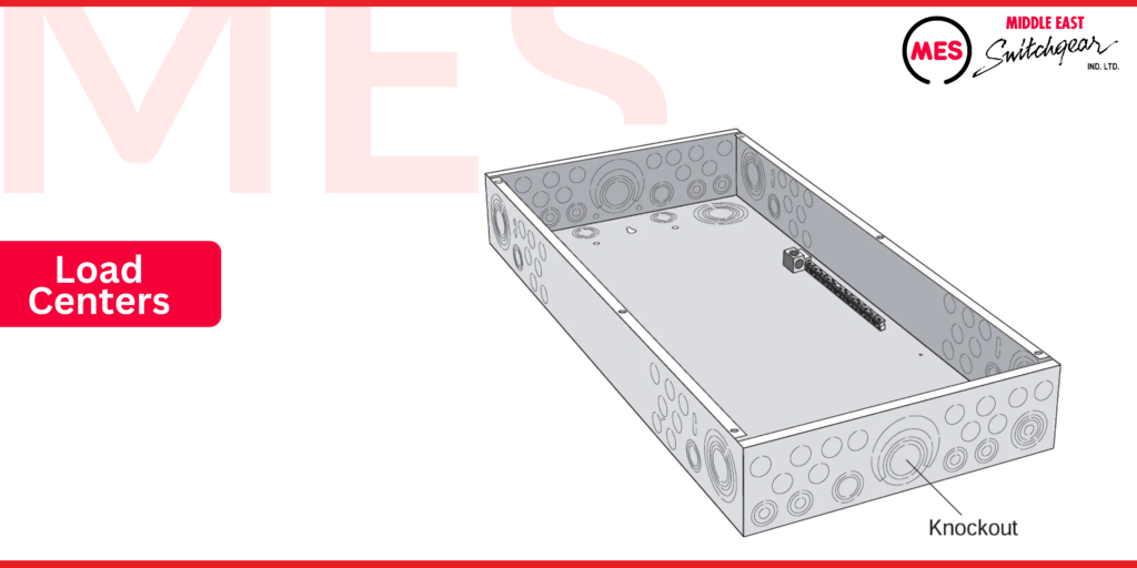
Load center enclosures generally conform to one of these NEMA enclosure types. They include knockouts stamped into the enclosure, providing a convenient means for creating holes to route electrical wiring. Approved cable clamps or conduit hubs are used in these holes to secure and protect the cables and conductors.
Removing Knockouts
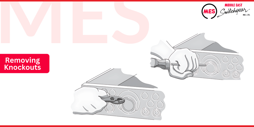
Knockouts can be removed from the enclosure before mounting it. For multiple-ring knockouts, follow these steps:
- Remove the Center Section: Strike the knockout at the point furthest from the tie to detach the center section.
- Break the Tie: Bend the knockout back and forth to break the tie and free the section.
- Create Larger Openings: If a larger opening is needed, remove each additional ring one at a time. As illustrated in the figure below, use a screwdriver to pry and pliers to bend the ring back and forth.
This process allows for convenient routing of electrical wiring and ensures a secure fit for cable clamps and conduit hubs.
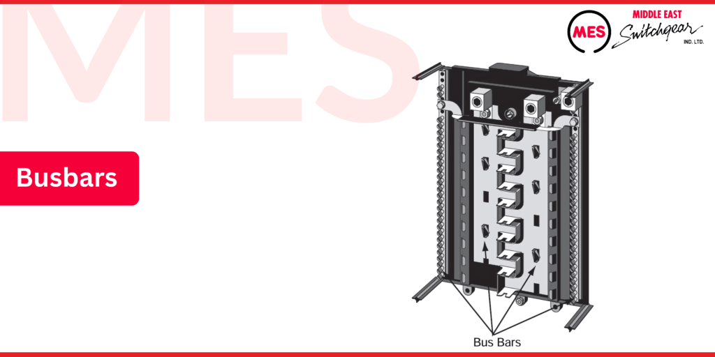
The load center interior mounts inside the enclosure and includes essential components such as bus bars and related hardware. This interior setup is crucial for distributing electrical power efficiently and ensuring the proper operation of overcurrent protection devices.
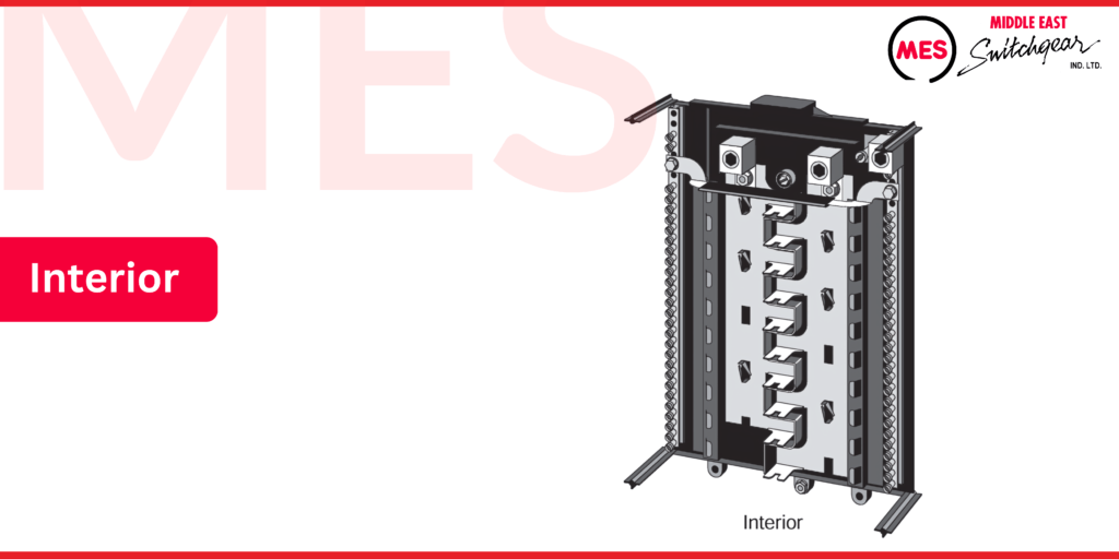
Bus Bars
A bus bar acts as a common connection point for two or more circuits. In a load center, bus bars facilitate the connection of circuit breakers to service conductors and load wiring, simplifying the electrical setup.
MES load center bus bars are typically made of copper or aluminum, offering reliable performance and durability for efficient electrical power distribution.
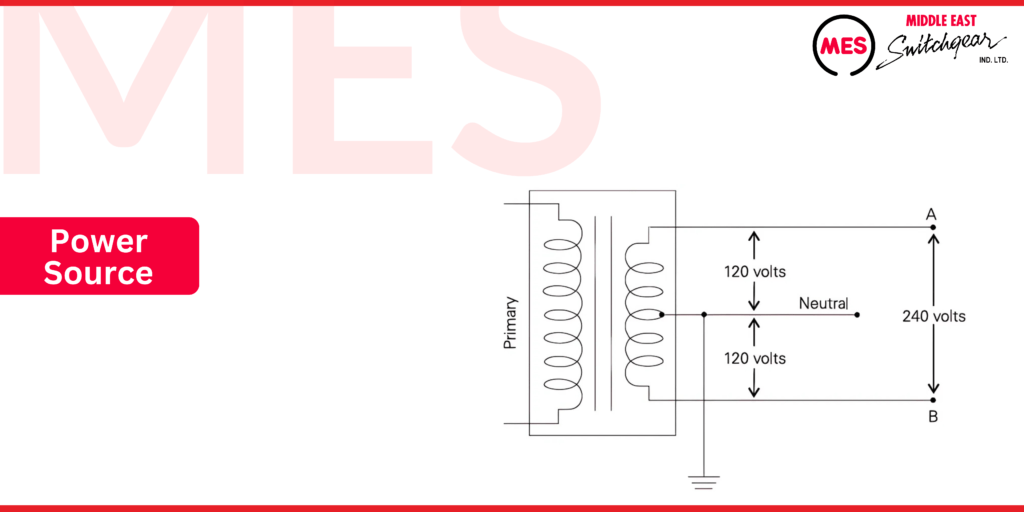
Power Source
The most common method for powering a load center involves connecting its supply bus bars to the secondary winding of the utility transformer. Even though the secondary winding provides single-phase power, one side is designated as the A phase and the other as the B phase.
The center tap connection of this transformer is grounded and serves as the neutral connection. This neutral is a current-carrying conductor that connects to the load center’s neutral bus.
As illustrated, with this configuration, the voltage applied to the load center’s supply bus bars is 240 volts. However, the voltage from the neutral connection to either supply bus bar is 120 volts.
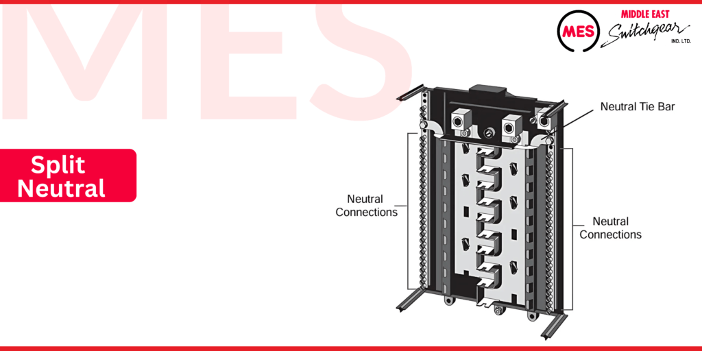
Split Neutral
Some MES PL series and MES ES series load centers feature dual neutrals. This means that neutral connections are available on both sides of the load center’s interior. The dual neutrals are interconnected through a neutral tie bar.
Dual neutrals are particularly useful in larger load centers as they simplify load center wiring, making installation and maintenance more efficient.
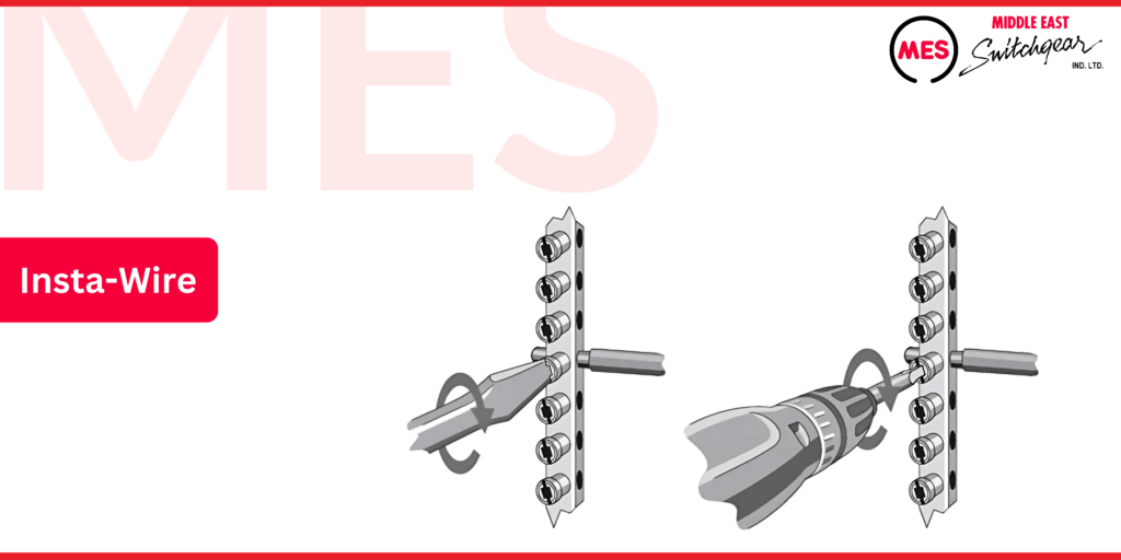
Insta-wire
MES’ PL and ES Series load centers come equipped with the Insta-Wire feature, designed to streamline installation. This innovative system includes factory-backed screws, secured in place by a special thread design. This feature prevents screws from falling out during shipment or installation, ensuring a hassle-free setup.
The Insta-Wire screws are compatible with both standard screwdrivers and square tool bits, making installation easier. By eliminating the need to manually back out screws, Insta-Wire allows installers to use power tools, significantly saving time and effort on the job.
This feature enhances productivity while providing reliable, secure connections for any electrical installation project.
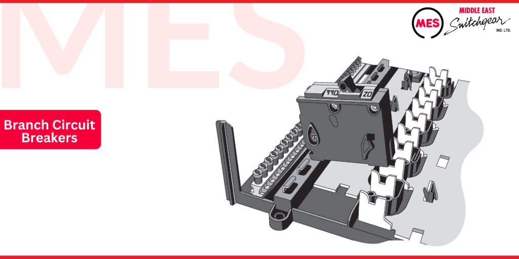
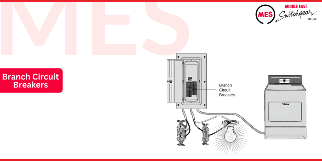
Branch Circuit Breakers
Branch circuit breakers plug directly into the load center’s supply bus bars as shown in the following illustration.
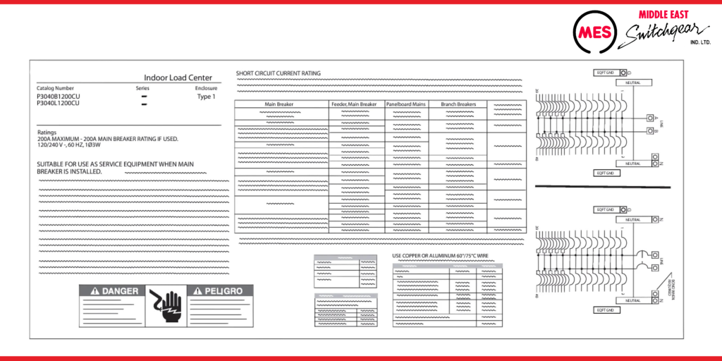
The label on a load center provides crucial details, including the catalog number, enclosure type, voltage service, and ampere rating. This information ensures that installers select the correct load center for their project needs.
In addition, the label specifies the types of circuit breakers compatible with the load center, short-circuit current ratings, and even wiring diagrams. These details help ensure safe and accurate installations, while guiding professionals on selecting the right components for reliable performance.
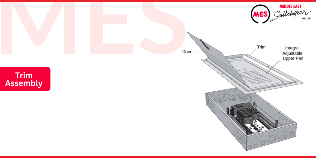
Trim Assembly
The trim assembly, also known as the dead front, attaches to the front of the load center and provides a protective cover for the interior components. It includes an access door and an adjustable upper pan for flexibility during installation.
The trim assembly offers easy access to the circuit breakers while securely sealing off live parts and internal wiring, ensuring safety and preventing accidental contact with energized components. This design prioritizes both accessibility and safety for electrical professionals.
Twistouts
The upper pan of the load center features twistouts, designed to cover any unused pole spaces that aren’t occupied by a circuit breaker. These twistouts can be easily removed using an up-and-down twisting motion with pliers.
For safety, all unused openings in the upper pan must be covered with a filler plate. This ensures that exposed spaces are securely sealed, preventing accidental contact with live components and maintaining the overall integrity of the load center.

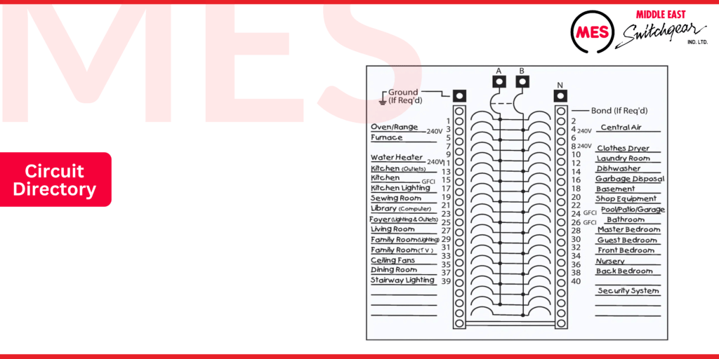
Circuit Directory
The circuit directory located on the door of the load center offers a designated space for listing the services protected by each branch circuit breaker. This directory simplifies identifying which breaker corresponds to specific circuits, enhancing organization and efficiency for users. By maintaining an updated circuit directory, you can easily manage electrical services and quickly respond to any issues that arise.
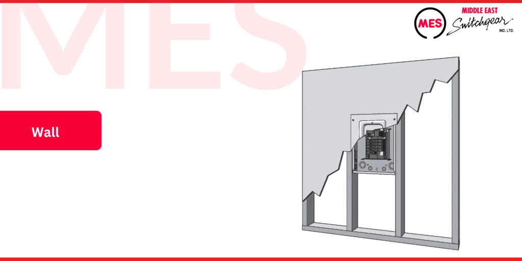
Load Center Installation
The. enclosure with the interior is mounted to a wall All Incoming and outgoing conductors are connected to the Load Center.
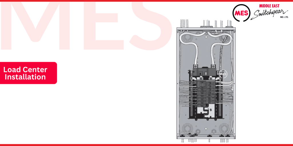
MES load centers offer flexible installation options, allowing for either surface or flush mounting. In flush-mounted setups, the load center is positioned so that the front edge of the enclosure aligns perfectly with the finished wall, creating a clean, seamless appearance.
Once the wall is completed, the trim assembly is installed, providing both protection and easy access to the internal components. This versatility makes Siemens load centers suitable for a variety of residential and commercial applications.
NEC® Article 110.26
Proper load center installation requires careful planning to create a safe environment for both personnel and equipment. Article 110.26 of the National Electrical Code® (NEC) outlines the requirements for spaces around electrical equipment. The goal of this code is to ensure there is sufficient working space for professionals to safely examine, adjust, service, and maintain energized equipment.
By following NEC guidelines, installers can enhance safety, reduce risks, and ensure that the load center remains accessible for future maintenance and inspections.
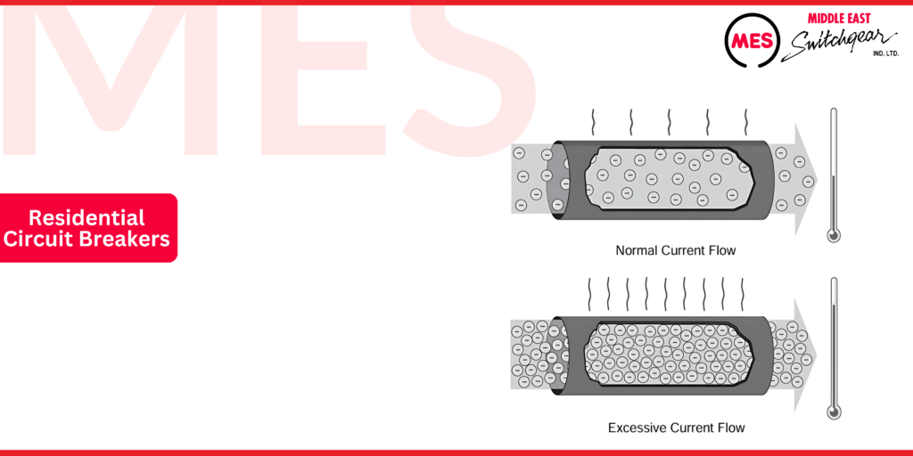
Residential Circuit Breakers
When current flows through a conductor, it naturally generates heat. The greater the current, the hotter the conductor becomes. Excess heat can damage electrical components, which is why conductors have a specified ampacity—the maximum current they can carry continuously without overheating.
When current exceeds safe levels, it’s called overcurrent, which can be caused by a short circuit, overload, or ground fault. In residential settings, load centers use circuit breakers to protect against short circuits and overloads. However, most residential circuit breakers do not include ground fault protection, so additional measures may be required for specific installations to guard against ground faults.
This ensures that homes are protected from potential electrical damage and safety hazards.
A short circuit happens when two bare conductors come into contact, causing a sharp drop in resistance at that point. This sudden reduction in resistance results in a rapid increase in current, which can severely damage electrical systems if not quickly addressed.
On the other hand, an overload involves a much lower current than a short circuit. It occurs when too many devices are connected to a circuit or when electrical equipment is forced to operate beyond its rated capacity. While the current rises more gradually, it can still lead to overheating and potential damage if not protected by a circuit breaker.
Both scenarios present risks, and residential circuit breakers are designed to handle these issues, ensuring the safe operation of home electrical systems.
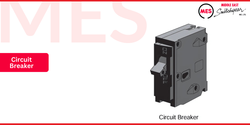
Circuit Breakers
Circuit breakers serve two important functions: they provide a manual way to energize and de-energize a circuit, and they offer automatic overcurrent protection. Unlike fuses, which need to be replaced once they “blow,” circuit breakers can be reset after the overcurrent issue is resolved.
To reset a circuit breaker, simply push the handle to the “OFF” position and then back to “ON”. This restores the circuit to normal operation. However, if the breaker trips again immediately after resetting, it’s a sign of a persistent issue. In such cases, it’s essential to consult a qualified electrician to identify and resolve the problem safely.
In an ideal scenario, overloads and short circuits wouldn’t occur, eliminating the need for circuit protection. However, in reality, these issues can and do happen. To safeguard circuits from damage, a circuit breaker must detect when a fault condition develops and automatically disconnect the electrical equipment from its voltage source.
While slight overloads can be tolerated briefly, allowing the circuit to operate for a short period, the circuit breaker must act more quickly as the current magnitude increases. In the case of short circuits, immediate disconnection is crucial, as these events require the breaker to open the circuit instantly to prevent severe damage and potential hazards.
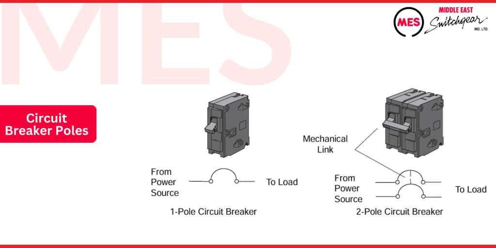
Circuit Breaker Poles
A circuit breaker’s pole number refers to the number of circuits it controls. For instance, a 1-pole circuit breaker handles current for a single circuit, while a 2-pole circuit breaker carries current for two circuits simultaneously.
In a 2-pole breaker, both circuits are connected to the same trip unit, meaning both poles will open together in the event of an overcurrent. Additionally, these circuits are mechanically interlocked, ensuring they can be manually opened or closed at the same time, providing synchronized protection and control. This feature is especially important in residential applications where higher voltage or current capacity is required.
Circuit Breaker Ampere Rating
Each circuit breaker comes with specific ampere, voltage, and interrupting ratings. The ampere rating indicates the maximum continuous current the breaker can handle without tripping. This rating is crucial because the circuit breaker’s main function is to protect circuit conductors from damage due to excessive current.
The appropriate ampere rating for a circuit breaker depends on the ampacity of the conductors in the circuit. Selecting the correct ampere rating ensures that the breaker will trip when necessary, preventing overheating and potential hazards in residential electrical systems.
Circuit Breaker Voltage Rating
A circuit breaker’s voltage rating indicates the maximum voltage it can safely handle. The breaker’s voltage rating must be at least equal to the voltage of the circuit it is protecting. In some cases, circuit breakers come with a “slash” voltage rating (e.g., 120/240 volts). This means the breaker can be used in a circuit where the voltage between any conductor and ground does not exceed the lower rating, and the voltage between conductors does not exceed the higher rating.
In residential applications, the most common power distribution system is the single-phase, 3-wire system. In these setups, a 1-pole circuit breaker typically protects a 120-volt branch circuit, while a 2-pole circuit breaker protects a 240-volt branch circuit, ensuring safe operation and protection across different voltage levels.
Circuit Breaker Interrupting Rating
A circuit breaker’s interrupting rating defines the maximum available fault current that the breaker is designed to interrupt safely. This rating ensures that, in the event of a fault—such as a short circuit—the breaker can effectively disconnect the circuit to prevent damage to electrical systems and reduce the risk of fire or injury. Choosing a circuit breaker with an appropriate interrupting rating is essential for ensuring reliable protection in residential and commercial electrical installations.
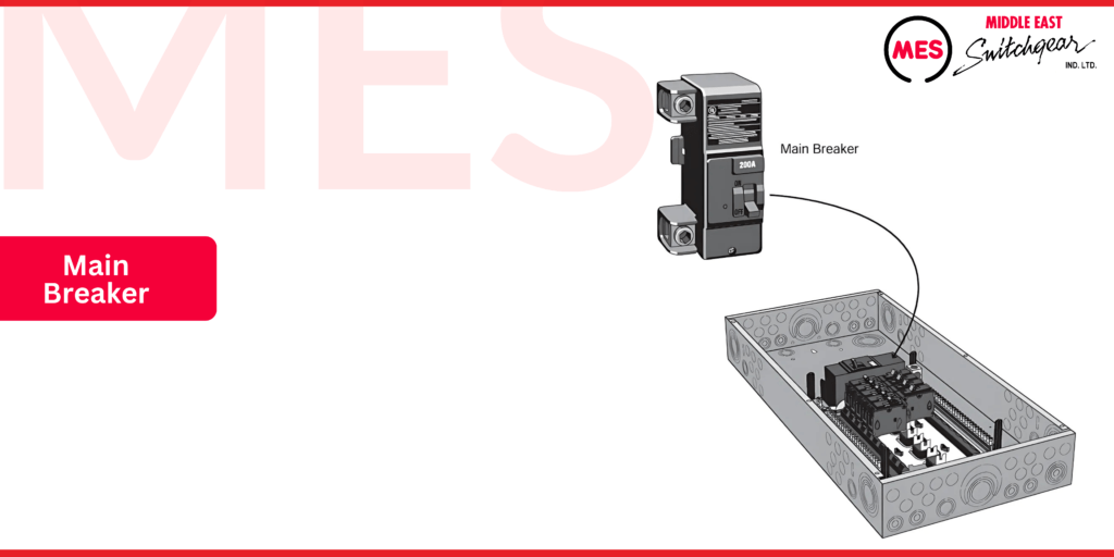
Main Circuit Breaker
Understanding the difference between a main circuit breaker and branch circuit breakers is crucial for effective electrical management. The main circuit breaker for a load center controls power to the entire load center and all circuits it supplies. When the main breaker is turned off, it shuts down power to all connected circuits, providing a critical safety mechanism.
The ratings of the main circuit breaker also determine the overall ratings of the load center, including its capacity to handle current safely. This ensures that the entire electrical system operates within safe parameters, protecting both equipment and occupants from potential hazards.
MES provides a diverse range of load centers, available with either a main circuit breaker or main lug configurations. Notably, the MES PL Series load centers offer the flexibility to convert from a main lug setup to a main breaker configuration, and vice versa. This adaptability allows for customized electrical solutions, catering to various installation needs and preferences while ensuring reliable performance and safety.
Branch Circuit Breakers
Load centers are equipped with multiple branch circuit breakers, each responsible for providing circuit protection and manual control for one of the load center’s branch circuits. These breakers play a crucial role in safeguarding individual circuits from overloads and short circuits, while also allowing users to manually energize or de-energize specific circuits as needed. This enhances safety and flexibility in managing electrical systems within residential and commercial settings.
The most common branch circuit breakers used in Siemens load centers are full-sized 1-pole and 2-pole circuit breakers. However, Siemens also offers a variety of other circuit breaker types designed for use in load center branch circuits. This wide selection ensures that users can find the appropriate breaker to meet specific electrical needs, enhancing both safety and functionality in residential and commercial applications.
QP Circuit Breakers
Type QP circuit breakers are full-size breakers in 1-pole, 2-pole, or 3-pole configurations. The term “full-size” indicates that each circuit breaker has a width of 1 inch per pole, making them ideal for standard load center installations. These breakers are designed to provide reliable protection and flexibility across various residential and commercial electrical systems.
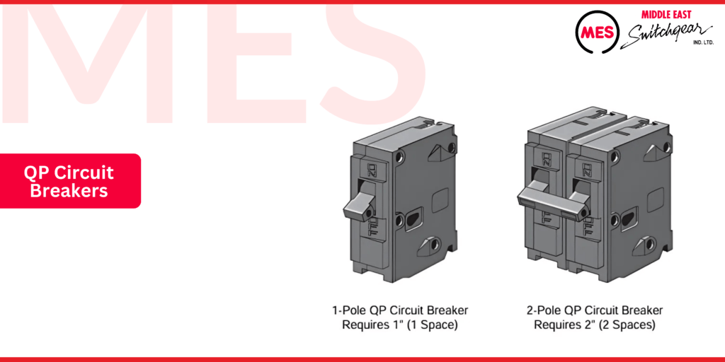
1-pole QP breakers are rated for 120 VAC and offer continuous current ratings ranging from 10 to 70 amps. For higher voltage needs, 2-pole QP breakers are available with either a 120/240 VAC or 240 VAC rating. The 2-pole 120/240 VAC breakers have continuous current ratings between 10 and 125 amps, while the 2-pole 240 VAC breakers range from 15 to 100 amps.
For more demanding applications, 3-pole QP breakers are rated for 240 VAC and offer continuous current ratings from 10 to 100 amps.
All Type QP circuit breakers come with a 10 kA interrupting rating. For higher fault current protection, Siemens also offers Type QPH breakers with a 22 kA interrupting rating and Type HQP breakers with a 65 kA interrupting rating. This range of options ensures comprehensive protection for a variety of residential and commercial electrical systems.
QP Circuit Breakers
Some MES load centers are designed to accept Type QT Duplex, Triplex, and Quadplex plug-in circuit breakers. These space-saving breakers are half the width per pole compared to Type QP breakers, allowing more circuits to be serviced from the same load center—provided that the main circuit breaker has sufficient capacity.
Type QT breakers are especially useful when additional circuits are needed in an existing load center with limited space. By reducing the width, these breakers maximize the number of circuits without requiring a complete panel upgrade, making them an ideal solution for expanding electrical systems in residential and commercial settings.
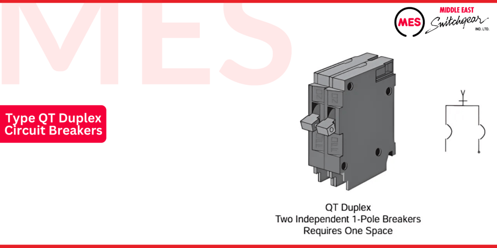
Type QT Duplex Circuit Breakers
Type QT Duplex circuit breakers combine two independent, half-inch wide breaker poles into a single, compact unit. This unit plugs into one load center stab and occupies just one-panel space, making it an efficient solution for adding circuits while conserving space in the load center. This design is ideal for installations where maximizing available panel space is essential, especially in expanding or upgrading existing electrical systems.
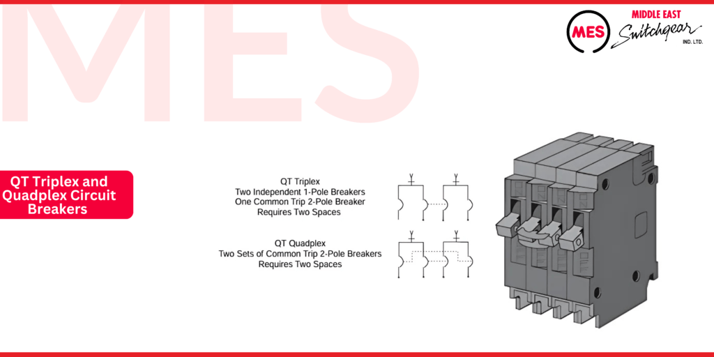
QT Triplex and Quadplex Circuit Breakers
Type QT circuit breakers are also available in Triplex and Quadplex configurations, offering versatile solutions for load centers.
- Triplex circuit breakers combine a 2-pole breaker for 120/240 VAC circuits and two independent 1-pole breakers for 120 VAC circuits, all in a single unit.
- Quadplex circuit breakers feature two common-trip 2-pole breakers for 120/240 VAC circuits, providing enhanced protection and control for multiple high-voltage circuits.
Each Triplex or Quadplex breaker requires two-panel spaces, making them an efficient way to service multiple circuits in limited space without sacrificing protection or functionality.
Ground Fault Protection
A ground fault occurs when a current-carrying conductor comes into contact with the ground. This can happen due to a faulty appliance or when water comes into contact with a conductor, creating a dangerous situation.
Ground fault protection is commonly achieved through the use of Ground Fault Circuit Interrupter (GFCI) receptacles, which replace standard outlets. Another method uses a GFCI circuit breaker, such as a MES Type QPF or QPHF GFCI breaker. Both types are available in 1-pole and 2-pole versions, protecting 120V and 240V circuits.
- Type QPF breakers have a 10 kA interrupting rating, while Type QPHF breakers offer a 22 kA interrupting rating for higher fault current protection.
Any receptacle connected to the same circuit as a QPF or QPHF GFCI breaker is ground fault protected, offering comprehensive safety. A GFCI works by comparing the current on the hot wire with the current returning on the neutral wire—under normal conditions, these currents are equal. If a discrepancy is detected, the GFCI trips, preventing potential electrical hazards.
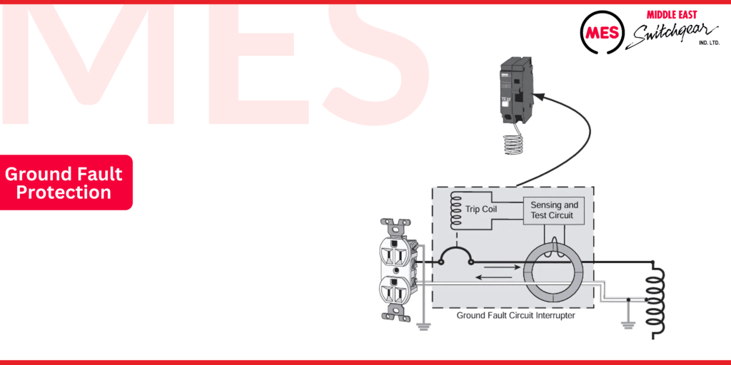
When a ground fault occurs, part of the current diverts to the ground through an alternate path. For instance, a ground fault can happen when an electrical appliance is placed on a wet surface, creating a new route for current to reach the ground. This situation puts anyone in contact with the appliance or the wet surface at risk of electric shock.
However, if the circuit is protected by a Ground Fault Circuit Interrupter (GFCI), the GFCI will detect the ground fault, open the circuit, and cut power to the appliance—effectively preventing injury and reducing the danger of electrical hazards.
Ground Fault Protection for Personnel
NEC® Article 210.8 outlines the requirements for Ground Fault Circuit Interrupter (GFCI) protection in various locations to safeguard personnel. Some of the most common areas that require GFCI protection for electrical receptacle circuits include:
- Bathrooms
- Residential garages
- Unfinished basements
- Within six feet of laundry, utility, or wet bar sinks
- Crawl spaces
- Outdoor areas
These regulations ensure enhanced safety in areas where moisture or other conditions increase the risk of ground faults and electric shock.
MES QPF and QPHF GFCI circuit breakers are specifically designed to protect personnel by sensing ground faults. These breakers will trip when they detect a fault current to ground of 6 mA or more. This quick response helps to minimize the risk of electric shock and enhances safety in areas where ground faults may occur.
Ground Fault Protection for Equipment
Ground Fault Circuit Interrupter (GFCI) protection is crucial for safeguarding equipment against harmful line-to-ground faults. MES QE and QEH circuit breakers are designed to de-energize the circuit when they detect a ground fault of 30 mA or more. The Type QE circuit breakers have a 10 kA interrupting rating, while the Type QEH circuit breakers feature a 22 kA interrupting rating. This range of ratings ensures effective protection in various applications. Both types are available in 1-pole and 2-pole versions, providing versatile options for protecting equipment.
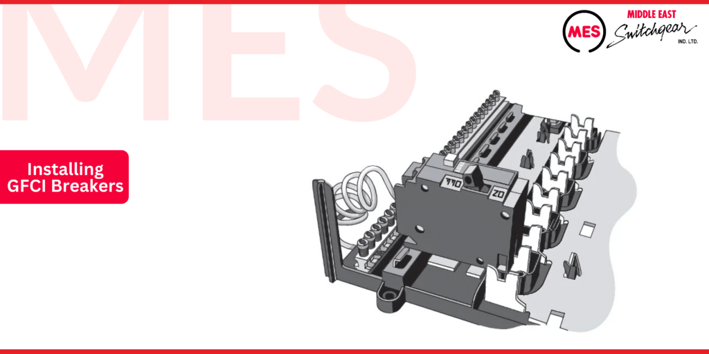
Installing GFCI Breakers
Siemens GFCI circuit breakers mount in a load center in the same way as a standard circuit breaker. However, they include one additional wire: a white “pigtail” neutral lead that connects to the load center’s neutral bus. These breakers are also equipped with a “Test” button that allows users to check the operation of the device after installation.
Arc Fault Protection
Arc Faults
Arc faults are undesired arcs in which current flows in unintended ways. In residential applications, these arcs usually do not generate enough current to trip a standard circuit breaker. Arc faults can occur for various reasons, including worn electrical insulation, damaged wiring, misapplied or damaged appliance cords and equipment, or loose electrical connections.
For example, if a staple is inadvertently driven through the insulation of a wire during installation, it could potentially cause arc faults to occur.
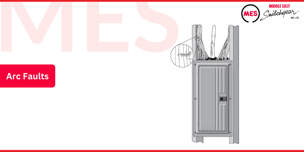
The arc fault problem is significant because each year, tens of thousands of fires are caused by electrical issues, with arc faults being one of the leading causes of these fires. Given that the causes of arc faults are numerous and often difficult to eliminate, detecting arc faults and shutting down affected circuits before property damage, personal injury, or loss of life occurs is even more critical.
AFCI Circuit Breakers
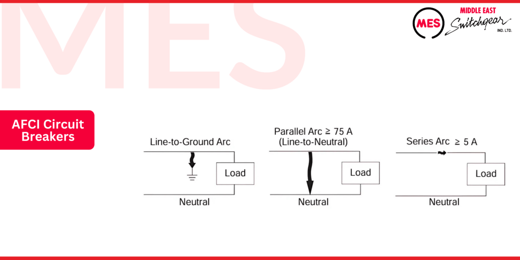
An Arc Fault Circuit Interrupter (AFCI) circuit breaker, in addition to providing overcurrent protection, is designed to offer a degree of protection against the effects of arc faults. It does this by recognizing the unique characteristics of arcing and de-energizing the circuit when an arc fault is detected.
There are two categories of AFCI circuit breakers. The first type, branch/feeder AFCI circuit breakers, not only provide overcurrent protection but are also designed to protect branch and feeder wiring from the damaging effects of line-to-ground arcs and high-energy parallel arcs. High-energy parallel arcs are defined as line-to-neutral arcs with a current greater than or equal to 75 A.
More recently, Combination AFCI (CAFCI) circuit breakers have been developed. In addition to providing overcurrent protection, CAFCI circuit breakers are designed to protect downstream wiring from three categories of arc faults: line-to-ground arcs, high-energy parallel arcs, and series arcs greater than or equal to 5 A. Series arcs occur on a single conductor.
NEC® Article 210.12
Requirements for arc fault circuit interrupter protection are outlined in NEC® Article 210.2. Over the years, the wording of this article has evolved. It’s important to refer to the appropriate version of the code for your location to determine the requirements for AFCIs and CAFCIs.
MES Type QAF AFCI circuit breakers have a 10 kA interrupting rating, while Type QAFH AFCI circuit breakers feature a 22 kA interrupting rating. Both breaker types are available in 1-pole and 2-pole versions.
MES AFCI circuit breakers are equipped with a white pigtail wire that attaches to the neutral bus. The 2-pole CAFCI circuit breakers feature two Test buttons, while all other MES AFCI circuit breakers have one Test button. These Test buttons are used to verify the device’s operation after installation.
MES CAFCI circuit breakers are equipped with LED trip indicators that assist electricians and homeowners in identifying the cause of a tripped breaker.
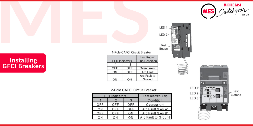
The MES 2-pole CAFCI is intended for a different application than most 2-pole circuit breakers. Instead of being used with one 240 VAC circuit, it is designed for use on two, 120 VAC circuits. The 2-pole CAFCI allows contractors to utilize multi-wire branch circuits, commonly known as shared neutrals, which helps reduce installation costs. While single-pole CAFCIs require a dedicated neutral for each circuit, the MES 2-pole CAFCI enables electricians to share neutrals between the two circuits supplied by the breaker.
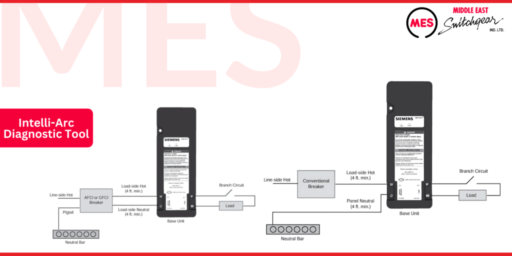
Intelli-Arc Diagnostic Tool
Although the LEDs on Siemens CAFCIs can guide an electrician in troubleshooting, these AFCIs do not pinpoint the specific portion of the branch circuit that contains a fault. Arc faults are often intermittent, making it challenging to identify the exact location of the issue within the branch circuit. In such cases, it is crucial to determine whether the fault condition exists in the permanent wiring, in connected equipment, or within a power cord.
The MES Intelli-Arc Diagnostic Tool assists in accurately diagnosing the circuit where a fault has occurred. This diagnostic tool can be used with any circuit breaker, regardless of the brand. When utilized alongside effective troubleshooting techniques, this tool enables electricians to locate the cause of the fault more quickly, ultimately saving money for each branch circuit that requires evaluation.
The Intelli-Arc Diagnostic Tool presents information regarding the type and magnitude of the fault. Since the fault may not trigger an AFCI to trip for various reasons—such as a duration that is too short or a current level that is too low—the tool offers an indication of how close an event is to causing an AFCI to trip.
As illustrated below, the Intelli-Arc Diagnostic Tool consists of a base unit, which is temporarily wired into a branch circuit, and a hand-held unit that wirelessly communicates with the base unit.
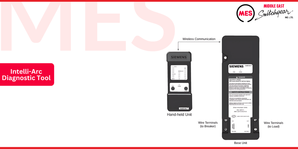
As the following illustration shows, the Intelli-Arc base unit can be easily wired into a branch circuit associated with an AFCI, GFCI, or conventional circuit breaker.
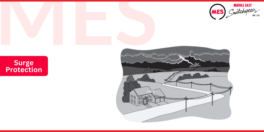
Surge Protection
Today’s homes contain numerous electronic devices, such as televisions, stereos, computers, and microwave ovens. These devices are highly susceptible to damage from electrical surges.
Electrical surges can be generated in the home by appliances such as vacuum cleaners and other motor-driven devices, as well as by spark igniters found on gas ranges, furnaces, and water heaters, among other equipment.
However, the most damaging surges are caused by lightning strikes. A lightning strike on a power line several miles away can still potentially cause extensive electrical damage in a home. While lightning strikes on high-voltage lines are generally dissipated by utility surge arresters, the average home experiences eight to ten voltage surges of 1,000 to 10,000 volts annually. Damage to expensive electrical equipment can be instantaneous if the surge is significant, but even moderate surges over time can lead to cumulative damage.
Thunderstorms
A typical lightning strike consists of 25,000 amps at 30 million volts. The following map illustrates the approximate mean annual number of days with thunderstorms across various regions of the United States.

Point of Entry Surge Protection
MES offers a variety of devices designed to minimize damage from electrical surges. One such device is the MES Circuit Breaker and SPD (surge protection device), which provides point-of-entry surge protection while incorporating two-pole circuit breakers. This device replaces two full-size, 15-amp, or 20-amp circuit breakers, offering surge protection for all branch circuits.
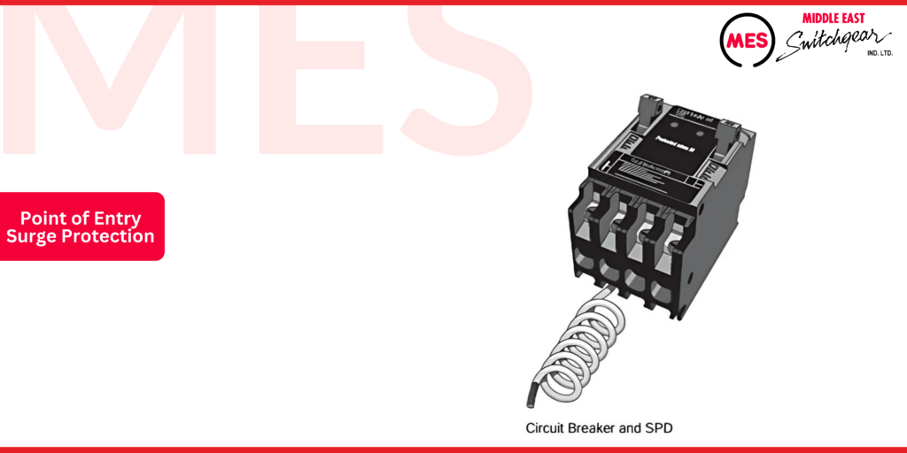
The Circuit Breaker and SPD incorporates two red LED indicator lights that illuminate to show that surge protection is provided for all circuits connected to the load center. It notifies the owner of any loss of surge protection by tripping one or both of the circuit breakers. The value of this feature is enhanced by using one of these breakers for circuit protection of frequently used household circuits, ensuring that the circuits controlled by the breaker also indicate the status of the surge protection.
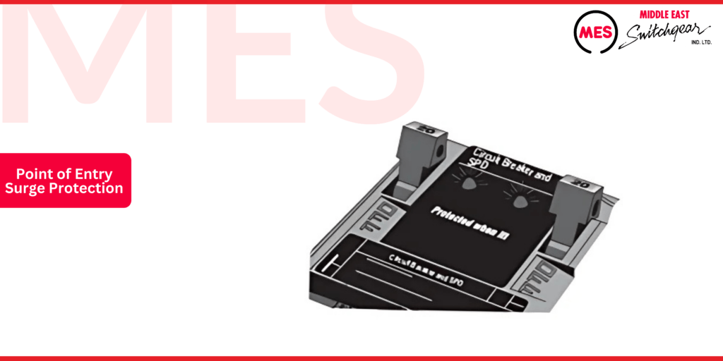
If one or both of the circuit breakers have tripped, turn both circuit breakers to the “OFF” position and then back to the “ON” position. If either light is not illuminated, the device may still be used for circuit protection; however, surge protection is no longer provided, and the device should be replaced by a qualified electrician.
Installation is straightforward, requiring only the mounting of a conventional circuit breaker in an MES load center. A lead wire is provided to connect the ground side of the module to the load center’s neutral bus. It is recommended to position the device in the first position of the load center and connect the lead wire in the first neutral position.
Load Center Mains
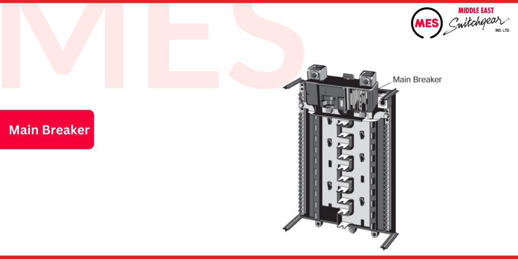
Main Breaker
There are two major categories of load centers: main breaker load centers and main lug only load centers. Some load centers, such as MES PL series load centers, can be converted from main breaker to main lug only or vice versa.
According to NEC® Article 408.36, a panelboard must have an overcurrent protection device with a rating that does not exceed the panelboard’s rating. This overcurrent protection device can be located within the panelboard or on the supply side of the panelboard. There are exceptions to this rule, so it is advisable to refer directly to the article for additional information.
Individual Protection
The following illustration demonstrates two approaches for applying overcurrent protection. If a main circuit breaker is located as an integral part of the load center, it is classified as a main breaker load center. Conversely, if a main circuit breaker is located remotely, then a main lug load center could be utilized. In this example, both the main breaker and the load center are rated for 200 amps.
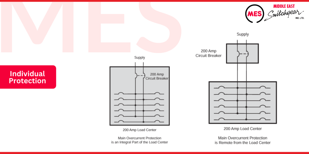
Main breaker load centers are commonly used in service entrance applications, where the incoming supply cables connect to lugs adjacent to the main breaker. This configuration allows the main breaker to feed power to the load center and its branch circuits. The main breaker serves two critical functions: it provides a means of manually disconnecting power from the load center and offers automatic overcurrent protection.
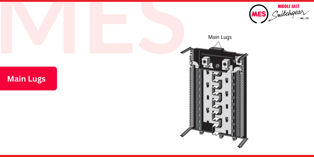
Main Lug Only
The following illustration shows the interior of a main lug-only load center. As the name suggests, main lug-only type load centers do not feature a main circuit breaker. Instead, the incoming supply cables connect directly to the main lugs and bus bars, facilitating the distribution of power to the branch circuits without the need for an integrated main breaker.
One common application for a main lug load center is as a subpanel. For instance, a main breaker load center might supply power to a main lug load center located in an area of the home designated as a workshop. It is important to ensure that the main breaker load center is appropriately sized to handle the additional load from the subpanel.
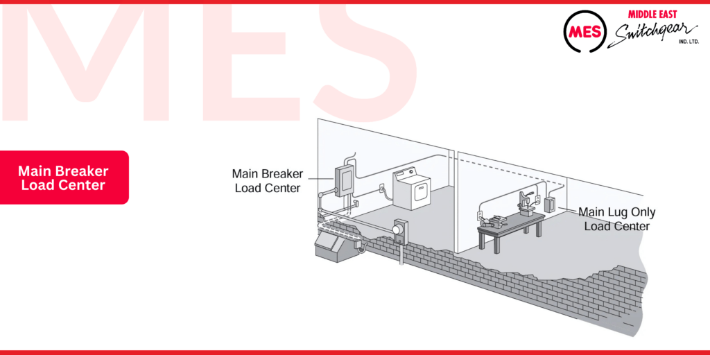
Main lug load centers are also utilized in various residential applications where the main breaker is situated remotely from the load center. For example, in apartment installations, main lug load centers are often employed since the main breakers and metering equipment are typically located in a more central position. This setup allows for efficient management of electrical distribution while keeping the main protective devices accessible.
Load Center Interrupting Ratings
NEC® Article 240.9 requires that circuit protection equipment have an interrupting rating sufficient for the available current. This requirement can be met through two approaches: the full rating method and the series rating method.
The full rating method ensures that the circuit breaker or fuse has an interrupting rating that matches or exceeds the maximum available fault current at the point of installation. This provides a straightforward and robust level of protection.
In contrast, the series rating method allows for a combination of devices to achieve an adequate interrupting rating while potentially reducing the overall size and cost of the protective equipment. In this method, a downstream device is rated for a lower interrupting current, while the upstream device, which must have a higher rating, protects the downstream device during fault conditions.
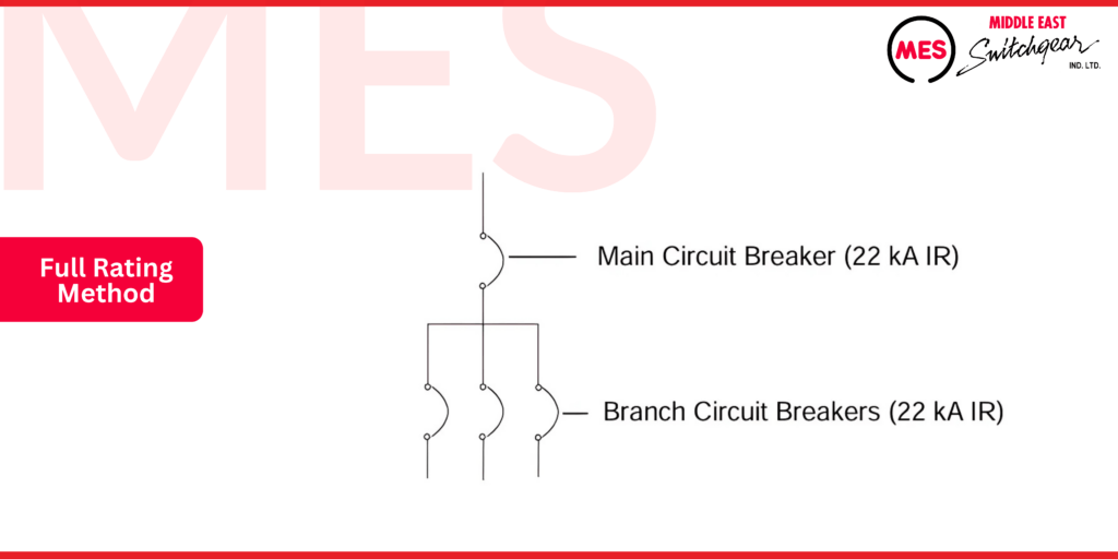
Full Rating Method
The full rating method mandates that all circuit protection devices possess an interrupting rating that is equal to or greater than the available fault current. In single-family homes, the available fault current typically does not exceed 10,000 amperes, making it relatively cost-effective to implement this method. By ensuring that each device meets or exceeds this requirement, homeowners can achieve reliable protection without incurring significant expenses.
In certain residential applications, the available fault current may exceed 10,000 amperes. For instance, in a building where the service entrance presents 22,000 amperes of available fault current, the full rating method necessitates that every circuit breaker possesses an interrupting rating of at least 22,000 amperes. This ensures that all protection devices can safely handle the potential fault conditions, safeguarding both the electrical system and the occupants of the building.
Series Rating Method
The series rating method also mandates that the main circuit protection device has an interrupting rating equal to or greater than the available fault current in the system. However, subsequent downstream circuit protection devices connected in series can be rated at lower interrupting values. For example, in a building with 22,000 amperes of available fault current, the main breaker at the service entrance must have at least a 22 kA interrupting rating. In contrast, downstream branch circuit breakers can possess a lower rating; in the following example, the downstream branch circuit breaker has a 10 kA interrupting rating.
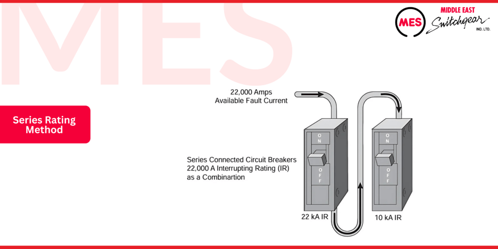
The series rating method is less expensive for the customer because it permits the use of branch circuit breakers with a lower interrupting rating. However, series-rated circuit breaker combinations must be tested in series to ensure they are UL-recognized. Additionally, NEC® Article 240.22 mandates that the series ratings must be marked on the enclosure to provide clear information regarding their capacity and compliance.
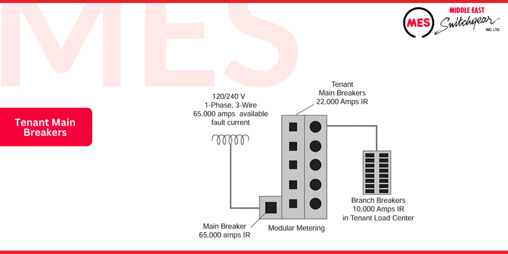
In larger installations, such as apartments, condominiums, and commercial facilities, the available fault current typically exceeds 10,000 amperes. In these situations, it’s common to see three-breaker series combinations. For instance, the main power supply of an apartment complex may present an available fault current of 65,000 amperes. Consequently, the main circuit breaker for a modular metering installation must be capable of interrupting this fault current. However, the tenant main breakers may only need to be rated for 22,000 amperes, while the branch breakers in each tenant’s load center might only require a rating of 10,000 amperes for fault current.
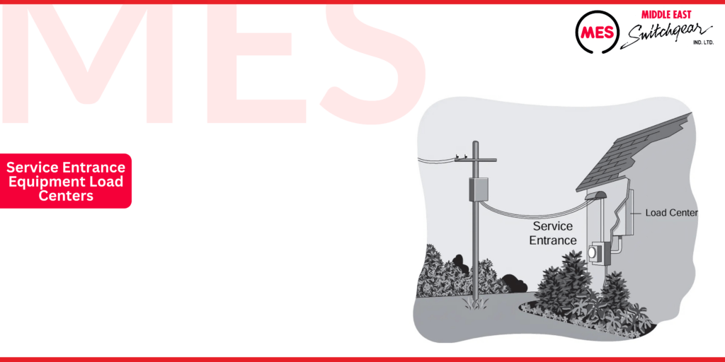
Service Entrance Equipment Load Centers
Load centers are often utilized as service entrance equipment for a building. This equipment is positioned near where the power supply enters the structure, connecting the incoming power supply to a system that allows for control and disconnection of the supply. Load centers must be designated for use as service equipment is listed and labeled as suitable for Service Entrance Equipment (SUSE).
Maximum Number of Disconnects for Service Entrance Equipment
Service-entrance conductors must feature a readily accessible means for disconnection from the power supply. According to NEC® Article 230.7, no more than six switches or circuit breakers can be employed to disconnect and isolate the service from all other equipment for each set of service entrance conductors. Typically, a main breaker load center serves as the service entrance panel, with the main breaker offering the necessary means for disconnection and isolation of the service.
Main lug-only load centers are generally not suitable for use as service entrance equipment, as this configuration would restrict the service entrance load center to no more than six circuit breakers.
Power Supply Systems
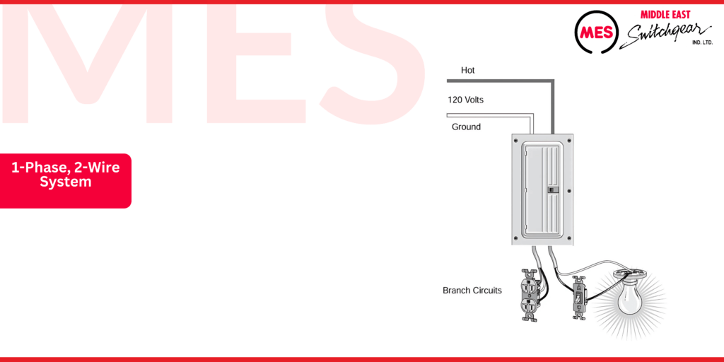
1-Phase, 2-Wire System
Homes built before 1936, particularly in rural areas, typically utilized a two-wire supply system. This system delivered 120 volts between a hot conductor and a grounded conductor. However, a two-wire system is generally insufficient for the electrical demands of modern residences and is not permitted for new construction.
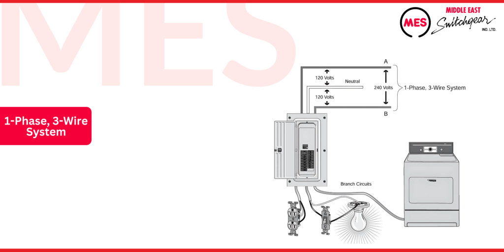
1-Phase, 3-Wire System
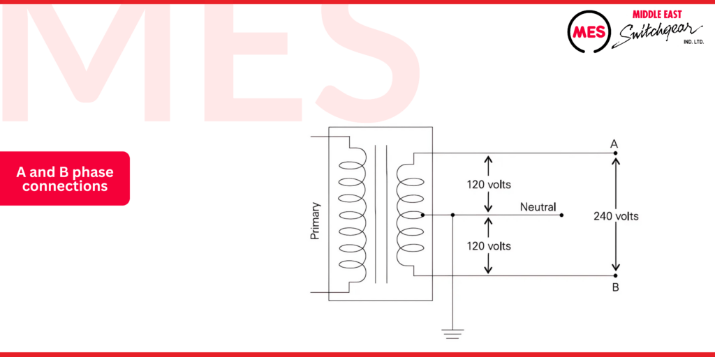
The most common supply system used in residential applications today is a single-phase, three-wire supply system. This configuration provides 240 volts from the A-phase connection to the B-phase connection, as well as 120 volts between either the A or B-phase connection and neutral.
The illustration demonstrates how the A and B phase connections, along with the neutral, connect to the secondary winding of the utility transformer. This setup is crucial for ensuring that residential electrical systems operate effectively, providing both 240 volts and 120 volts as needed for various appliances and devices.
Load centers can also be utilized in commercial applications that require three-phase power. Two of the more common approaches for providing three-phase power in these scenarios involve specific configurations of transformers and distribution systems. These approaches ensure that commercial facilities can efficiently distribute electrical power to accommodate their higher energy demands.
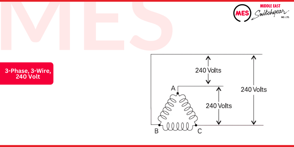
3-Phase, 3-Wire, 240 Volt
The following illustration depicts the utility transformer secondary windings for a three-phase, three-wire, 240-volt system. This configuration utilizes a delta transformer setup, where each phase delivers 240 volts. In a delta configuration, the phases are connected in a triangular formation, which allows for a balanced load and effective power distribution across all three phases. This type of system is commonly used in commercial and industrial settings due to its efficiency and capacity to handle larger electrical loads.
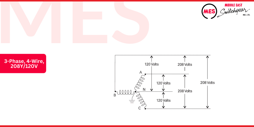
3-Phase, 4-Wire, 208Y/120V
There are multiple approaches for 3-phase, 4-wire services. The following illustration shows the utility transformer secondary windings for one of the more common approaches, a 3-phase, 4-wire, 120/208-volt system. This system uses a wye transformer configuration with a grounded neutral (N). This system provides 120 volts between any phase connection and neutral, and 208 volts between any two phases.
Load Center Grounding
An object connected to the earth is considered grounded. However, not all ground connections are intentional. Accidental grounding can occur due to faulty equipment or improper wiring. Proper intentional grounding, on the other hand, is crucial for the safe and reliable operation of electrical systems.
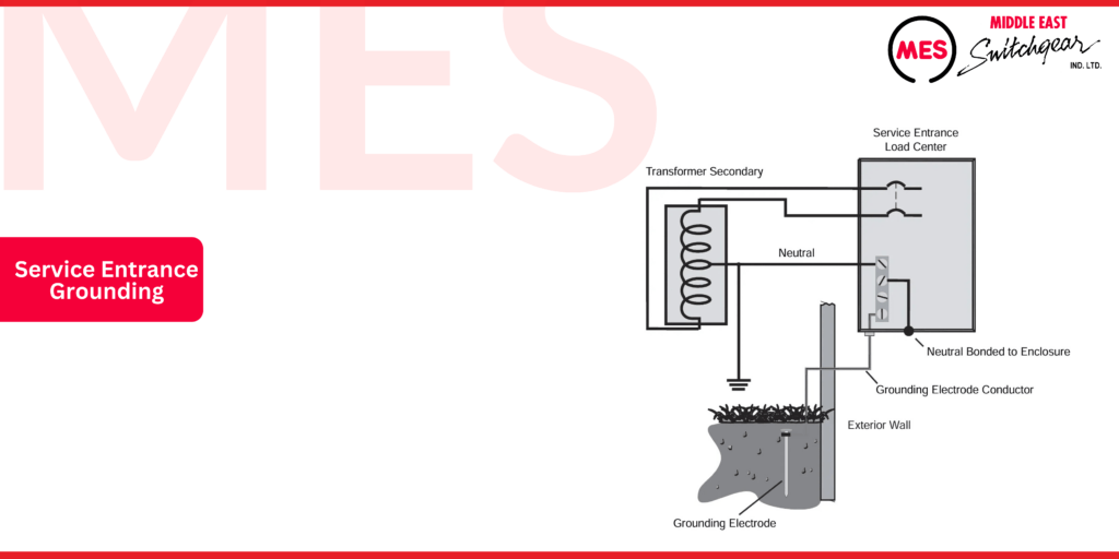
Service Entrance Grounding
When installing a load center, it’s crucial to ground the neutral bus only at the service entrance, as illustrated below. This is achieved by connecting a grounding electrode to either the ground or neutral bus. At the service equipment, the ground and neutral buses must be bonded to the enclosure, ensuring that both buses and the enclosure are grounded. The grounded neutral from the power source should also be connected to the neutral bus in the load center.
Bonding
Bonding refers to the joining of metallic parts to create a low-resistance electrical connection. This is typically achieved using a bonding screw that connects a bus to a metal enclosure. Depending on the equipment’s design, a metal bonding strap may also be necessary. MES PL and ES series load centers feature a pre-positioned bonding screw, which eliminates the need for bond straps or screw assemblies, reducing the risk of losing components during installation.
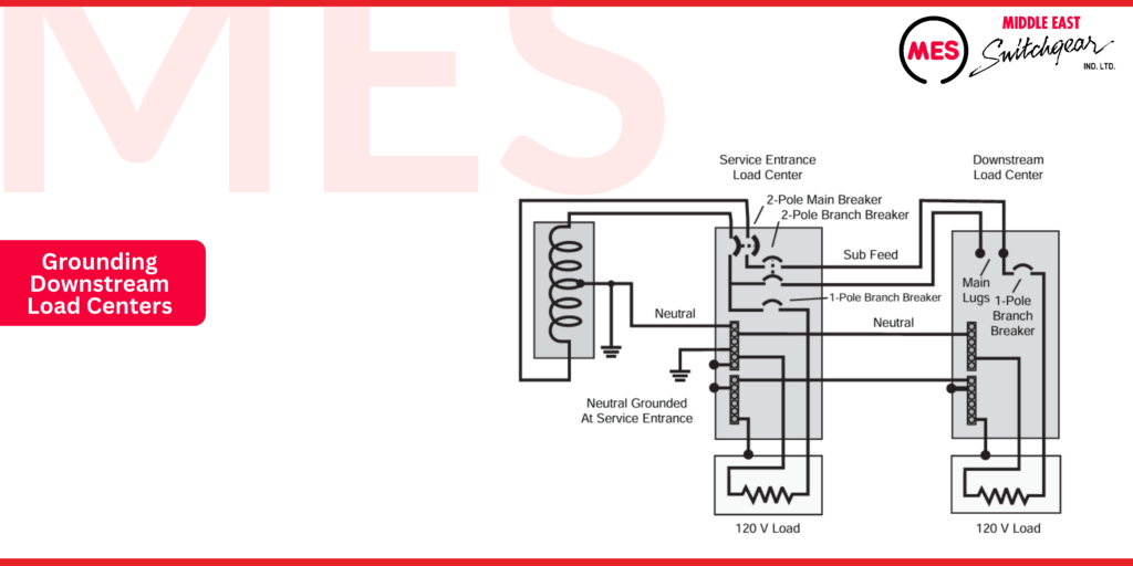
Grounding Downstream Load Centers
The neutral conductor is only directly connected to the ground at the service entrance. When a downstream panel is used, the neutral is insulated and isolated within that panel. The downstream panel must have a ground connection bonded to the enclosure. The equipment ground conductor links the downstream panel to the ground at the service entrance panel.
PL Series Load Centers
Features
Middle East Switchgear offers two primary load center product lines: the PL series and the ES series. The PL series load centers are designed with advanced features that ensure flexibility, ease of installation, and durability:
- Convertible from the main breaker to the main lug, and vice versa
- Invertible for bottom-feed applications
- Insta-wire neutrals and grounds for faster installation
- Ground bus bars included for convenience
- Copper bus bars for superior conductivity
- Dual neutrals on all configurations
- Carton-in-carton packaging, with trims packaged separately to prevent damage
- Lifetime warranty for peace of mind
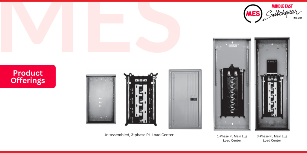
Product Offerings
The PL series load center product line from Middle East Switchgear offers a wide range of variations to meet any application requirement. Below is a summary of its versatile capabilities:
- 1-phase or 3-phase mains options
- Main breaker or main lug configurations
- 2 to 70 circuits/spaces for various needs
- Indoor and outdoor enclosures for different environments
- 100 to 225 amp current ratings for flexible power demands
- Un-assembled offering for 3-phase systems
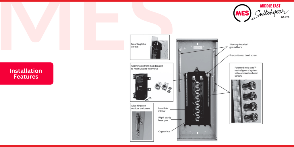
Installation Features
PL series load centers from Middle East Switchgear are engineered for quick and easy installation. Below are examples of the installation features that enhance efficiency:
- Middle East Switchgear’s patented Insta-wire screws on neutral and ground buses are captive, preventing loss of screws and ensuring a faster wiring process by being backed out at the factory.
- A pre-positioned bonding screw is designed to eliminate the need for bonding straps or separate screw assemblies.
- Two ground bars are factory-installed on all PL load centers for added convenience.
- Slot/square combination screw heads on the neutrals, ground, trim, upper pan, and bond screws offer flexibility during installation.
- The interior can be easily inverted for bottom-feed applications.
- Load center mains can be converted from the main breaker to the main lug, and vice versa.
- Mounting tabs on the trim hold it securely in place during installation, allowing for hands-free operation while driving trim screws.
- The outdoor enclosure features a slide hinge for ease of installation.
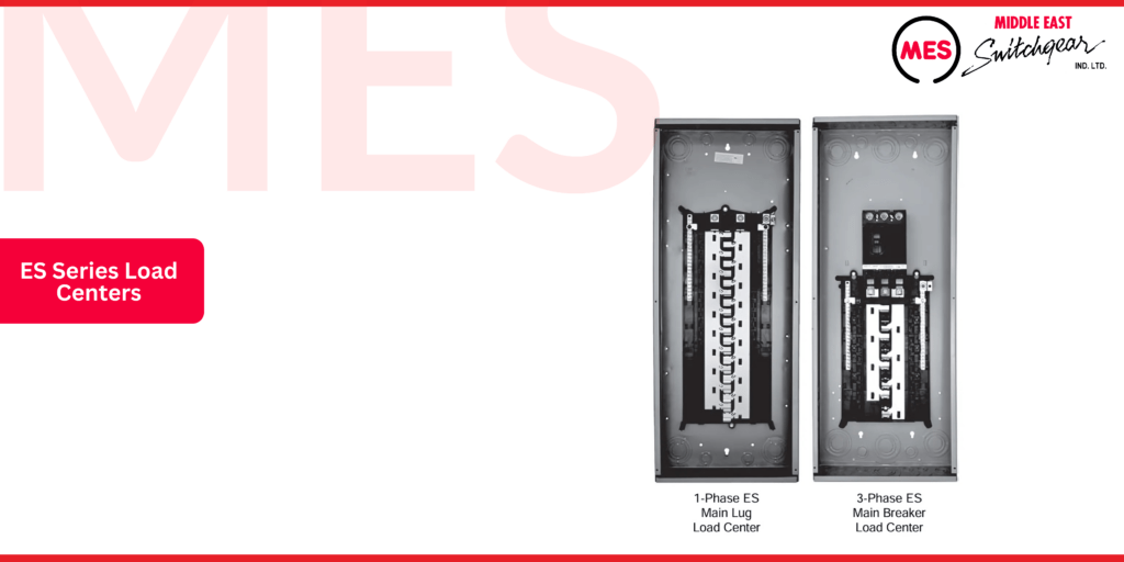
ES Series Load Centers
Features
ES series load centers from Middle East Switchgear offer the following features:
- Invertible for bottom-feed applications
- Insta-wire neutrals and grounds for quicker installation
- Aluminum bus bars for lightweight efficiency
- Single-sided neutrals on load centers with 24 circuits or fewer
- Single-piece carton for easy handling and storage
- 10-year warranty for added peace of mind
Product Offerings
The ES series load center product line from Middle East Switchgear offers a wide array of variations to meet any application need. Below is a summary of its diverse capabilities:
- 1-phase or 3-phase mains options
- Main breaker or main lug configurations
- 2 to 70 circuits/spaces for flexibility
- Indoor and outdoor enclosures for various environments
- 100 to 225 amp current ratings to suit different power demands
- Value packs—a mix of branch breakers provided with the load center
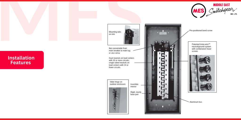
Installation Features
ES series load centers from Middle East Switchgear are engineered for quick and easy installation. Below are examples of the installation features that enhance efficiency:
- Middle East Switchgear’s patented Insta-wire screws on the neutral and ground are captive, preventing loss of screws and ensuring a faster wiring process by being backed out at the factory.
- A pre-positioned bonding screw is designed to eliminate the need for bonding straps or separate screw assemblies.
- Slot/square combination screw heads on the neutrals, ground, trim, upper pan, and bond screws provide installation flexibility.
- The interior can be easily inverted for bottom-feed applications.
- The main lug and main breaker load centers are available, but the mains are not convertible.
- Mounting tabs on the trim hold it securely in place during installation, allowing for hands-free operation while driving trim screws.
- The outdoor enclosure features a slide hinge for ease of installation.
MES EQ Load Centers
Middle East Switchgear manufactures a variety of EQ load centers, ranging from circuit breaker enclosures and small circuit load centers to 300-400 amp 1-phase and 3-phase load centers.
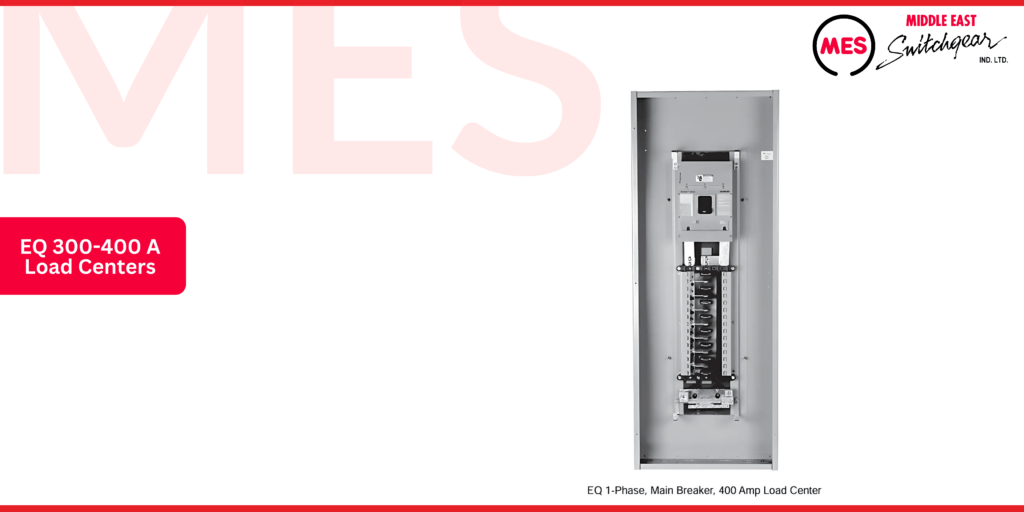
EQ 300-400 A Load Centers
Middle East Switchgear offers EQ 300 to 400 amp main breaker and 400 amp main lug load centers, suitable for 1-phase, 3-wire 120/240V and 3-phase, 3-wire, and 4-wire 240V applications. Load center sizes range from 24 to 42 circuits. Both indoor (NEMA 1) and outdoor (NEMA 3R) enclosures are available.
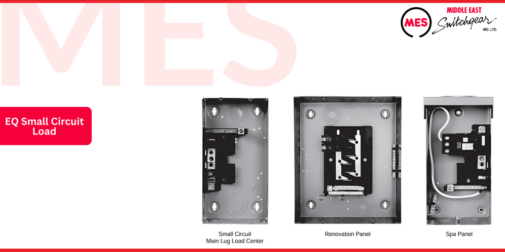
EQ Small Circuit Load
Middle East Switchgear offers EQ small circuit load centers, designed as 1-phase, 3-wire 120/240V load centers available with either main lugs or main breaker configurations, featuring copper bus or aluminum bus options. Both indoor (NEMA 1) and outdoor (NEMA 3R) enclosures are available.
EQ small circuit load center sizes range from 4 to 20 circuits and 100 to 200 amps. The product line includes renovation panels and spa panels.
Renovation panels are ideal for older home projects where the distance between studs is narrower than current construction practices. This narrower panel eliminates the need to notch out existing studs. Spa panels are designed for outdoor applications, such as hot tubs, that require ground fault protection. A factory-installed 2-pole GFCI breaker is included, along with two extra circuits.
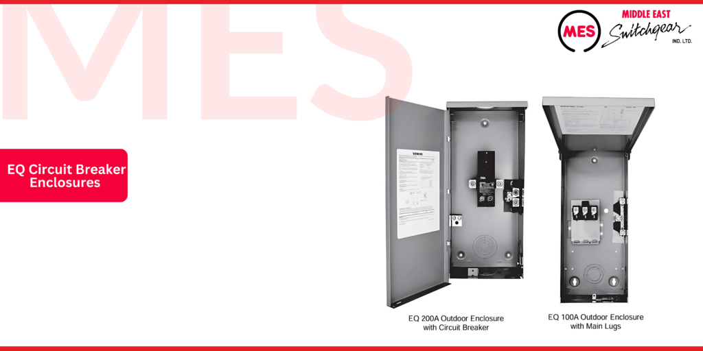
EQ Circuit Breaker Enclosures
Middle East Switchgear offers EQ circuit breaker enclosures designed for use with QP, QT, QPH, HQP, BQ, BQH, HBQ, QPP, QPPH, HQPP, QJ2, QJH2, and QJ2-H circuit breakers. Both indoor (NEMA 1) and outdoor (NEMA 3R) enclosures are available.
EQ circuit breaker enclosures for 1-phase, 3-wire 120/240V applications are offered with ampere ratings ranging from 60 to 225 amps. Additionally, enclosures for 3-phase, 3-wire 240V, and 3-phase, 4-wire 120/208V, 120/240V, and 240V applications are available with 200 or 225 amp ratings.
Generator Ready Load Centers
The Generator Ready Load Center from Middle East Switchgear is a 200 or 225-amp, 30-circuit, 42-space load center designed to provide an effective solution for implementing generator backup for critical circuits. Both main lug and main breaker versions are available with indoor (NEMA 1) or outdoor (NEMA 3R) enclosures.
Main lug load centers can be converted to main breaker load centers and vice versa with the appropriate conversion kit. These load centers feature two interiors, where up to 30 critical circuits are wired to the lower interior, while non-critical circuits are wired to the upper interior. During normal operation, both interiors are powered by the electrical utility. When utility power is unavailable, the critical circuits connected to the lower interior can be switched to generator power.
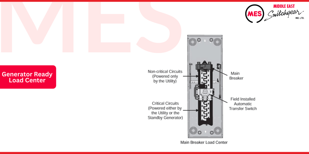
To implement generator backup functionality, either an automatic transfer switch or a manual transfer switch must be installed. The switch, along with any branch circuit breakers required for the application, must be ordered separately. However, installing the load center without the transfer switch is a cost-effective approach for new construction when a generator will not be initially installed. This strategy allows the necessary wiring for standby generator operation to be completed during the initial construction phase. Later, the homeowner can install a standby generator without incurring the cost of rewiring.
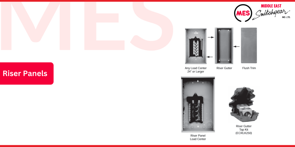
Riser Panel Load Centers
Riser Panels
Riser panels from Middle East Switchgear are designed for use in high-rise applications. The interior of the riser load centers is shifted to the left, providing extra room for riser cables to pass through. Middle East Switchgear’s main lug riser panels are available with 125 or 200 amp ratings, and main breaker conversion kits can be provided.
The panels can be mounted with main lugs on top or inverted to allow cables to pass on the opposite side. These riser panels are 1-phase only but can be fed from 1-phase or 3-phase systems running through the gutter. The riser gutter tap kit (ECRLK250) enables the installer to tap off the main conductors. If an existing Middle East Switchgear 1-phase or 3-phase load center (24 inches or larger) is used instead of the riser panel load center, the riser gutter (RAG24) can be installed to convert the load center into a riser panel.
Included with the riser panels are load center mounting hardware, a passthrough brush, and flush trim.
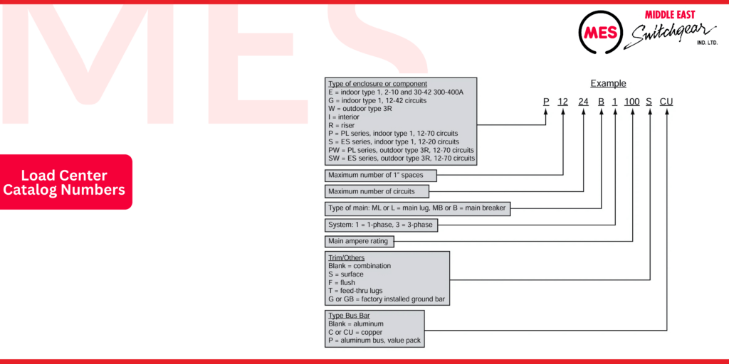
Load Center Catalog Numbers
Middle East Switchgear load centers utilize an eight-part catalog number system; however, parts seven and eight may be blank depending on the chosen load center configuration. The following example (P 224B 00SCU) corresponds to a load center with the following characteristics:
- PL series indoor, type 1 enclosure
- Maximum of 2 spaces for 1-inch breakers
- Maximum of 24 circuits
- Main breaker 1-phase
- 200-ampere rating
- Surface mounting
- Copper bus bars
Sizing The Load Center
Planning is a crucial first step for all electrical projects. Careful engineering is required to ensure that the distribution system safely and efficiently provides adequate electrical service to both current and potential future loads. As part of this planning, procedures outlined in the NEC® should be followed to correctly size the load center based on the following characteristics:
- General lighting load based on the square footage of living space
- Small appliance load
- Laundry circuit load
- Large appliance load
- Miscellaneous appliance load
Power Calculations
When a force causes motion, work is accomplished. In an electrical circuit, the voltage applied to a circuit causes electrons to flow. Voltage is the force, and electron flow, measured in amps, is the motion. The rate at which work is done is called power.
The unit of measure for power depends on the type of power. For example, apparent power is the product of voltage (in volts) times current (in amps). Therefore, apparent power is expressed in volt-amps (VA). True power, on the other hand, is the product of apparent power times the power factor. True power is expressed in watts. For a more complete explanation of true power and apparent power, refer to the STEP course titled Basics of Electricity.
Manufacturers of electrical equipment often rate their products in watts based on power measurements taken with rated voltage and current applied. For many applications, such as the single-family home described on the following pages, power is expressed in VA when rated current and voltage are known, but the power factor is not known. The following example uses apparent power values, expressed in VA, to simplify the description and arrive at an approximate solution. More exact calculations are often needed to design circuits for real applications.
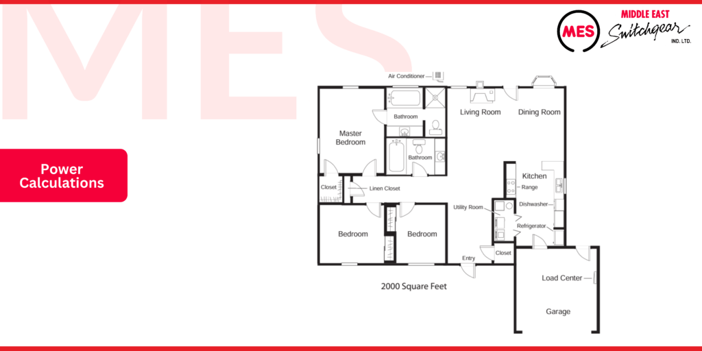
This sample floor plan is for a 2000 square foot home that has a 9600 VA (240 volts x 40 amps) air conditioner, a 9600 VA (240 volts x 40 amps) electric range, 2000 VA (240 volts x 50 amps) of electric heating, a 5000 VA (240 volts x 20.8 amps) clothes dryer, a 500 VA (120 volts x 2.5 amps) dishwasher, and a 76 VA (120 volts x 9.8 amps) garbage disposal. Three small appliance circuits will be used in the kitchen area.
Note: A thorough knowledge of the NEC® is required to properly size load centers and conductors. If you will be performing this task, you are encouraged to become familiar with this code.
General Lighting Load
According to NEC® Table 220.2, the minimum general lighting load for a dwelling is calculated at 3 VA per square foot of living space. This includes non-appliance receptacles for items such as table lights and television sets. The example has 2000 square feet of living space. The calculated living space does not include carports, garages, or unfinished spaces, such as basements, that are not adaptable for future use. The required general lighting load for this example is 6000 VA:
3 VA x 2000 square feet = 6000 VA
Small Appliance Loads
According to NEC® Article 210.11(C)(1), at least two 120-volt, 20-amp small appliance circuits must be provided. These are typically located in the kitchen area for small appliances like toasters and coffee makers. Additionally, NEC® Article 220.52(A) specifies that these circuits should be rated at 1500 VA. In this example house, there will be three small appliance circuits for a total rating of 4500 VA:
3 x 1500 VA = 4500 VA
Laundry Circuit
NEC® Article 210.11(C)(2) requires at least one 120-volt, 20-amp circuit for the laundry area. Article 220.52(B) also specifies that this circuit shall not be less than 1500 VA.
1500 VA
Total General Lighting and Small Appliance Load
From the previous calculations, the total general lighting and small appliance load is:
- General lighting: 6000 VA
- Small appliance load: 4500 VA
- Laundry circuit: 1500 VA
Total: 12,000 VA
Demand Factors
All residential electrical outlets are never used at one time. Because of this, the NEC® allows for a demand factor in sizing electric services. Demand factors for general lighting are provided in NEC® Table 220.42. The first 3000 VA is rated at 100%. The remaining 9000 VA (12,000 VA minus 3000 VA) can be rated at a demand factor of 35%.
- First 3000 VA at 100% = 3000 VA
- Remaining 9000 VA at 35% = 3150 VA
Net general lighting and small appliance load = 6150 VA
Large Appliance loads
Large appliance loads must be considered individually. The following large appliances are used in this example:
- Air conditioner: 9600 VA
- Electric clothes dryer: 5000 VA
- Electric heat: 12,000 VA
- Electric range: 9600 VA
Air conditioner and electric heat will not be used at the same time. Only the larger of the heater load or air conditioner load is used (NEC® Article 220.82(C)). In this case, the heater load (12,000 VA) exceeds the air conditioner load (9600 VA). All other large appliance loads must be calculated at 100%, except for the electric range. NEC® Table 220.55 allows a demand factor for electric ranges, as not all burners will normally be on a high at the same time. According to Table 220.55, an electric range with a rating not greater than 12,000 watts can have a demand factor of 8000 watts. For this calculation, assuming a power factor of 0.9, this results in an apparent power rating for the electric range of 8889 VA (8000 watts divided by 0.9).
- Electric heat: 12,000 VA
- Electric clothes dryer: 5000 VA
- Electric range: 8889 VA
Net large appliance load 25,889 VA
Miscellaneous Loads
Miscellaneous appliance loads must also be taken into consideration. The example includes the following miscellaneous appliance loads:
- Dishwasher: 1500 VA
- Garbage disposal: 1176 VA
Total miscellaneous appliance load: 2676 VA
Required Service
The required service size is determined by summing the calculated values:
- General lighting, laundry, and small appliance load: 6150 VA
- Net large appliance load: 25,889 VA
- Miscellaneous appliance load: 2676 VA
Total load: 34,715 VA
The average power supply for residential use is 120/240 volts. To find the required load center rating, divide the total load by 240 volts (the highest voltage used).
34,715 VA ÷ 240 volts = 144.6 amps
A load center rated for 150 amps could be selected. However, before selecting a load center, it’s important to plan for electrical service expansion by providing space for at least two future branch circuits. Since the load for these future circuits is undetermined, add ten amperes per space.
The amperage requirement is now:
144.6 amps + 20 amps (expansion) = 164.6 amps
Safety Factor
Circuit breakers are affected by the temperature of the air surrounding them. For this reason, an additional safety factor of 20% is added to the load center requirements.
164.6 amps + (0.20 x 164.6) = 197.5 amps
Therefore, a 200 amp load center is a good choice.
Determining the Number of Circuits
Calculating the number of circuits required in a load center involves an understanding of how circuits are configured. In the following example, a 20/240-volt power supply is connected to a 6-space/circuit load center.
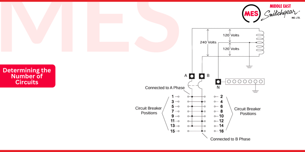
The term A phase refers to the part of a single-phase system between one hot wire and neutral. The term B phase refers to the part of a single-phase system between the other hot wire and neutral. Half of the circuits are connected to the A phase and half to the B phase. For example, circuits 1 and 2 are connected to the A phase; circuits 5 and 6 are connected to the B phase. The number of usable circuits in this load center depends on how many 20-volt and 240-volt circuits need to be connected to it. Each 20-volt circuit will use one of the circuit breaker positions. Each 240-volt circuit will use two of the circuit breaker positions.
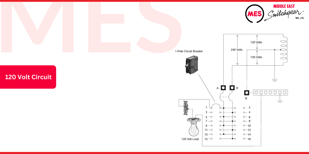
120 Volt Circuit
A circuit requiring 20 volts, such as general lighting and electrical receptacles, is connected through a 1-pole circuit breaker. In the following example, a 1-pole circuit breaker has been installed in position 1. A lighting circuit receives 20 volts from A phase, through the circuit breaker and returns to the neutral connection. Power to the light can be interrupted by the light switch. There are 5 circuit breaker positions left for additional circuits.
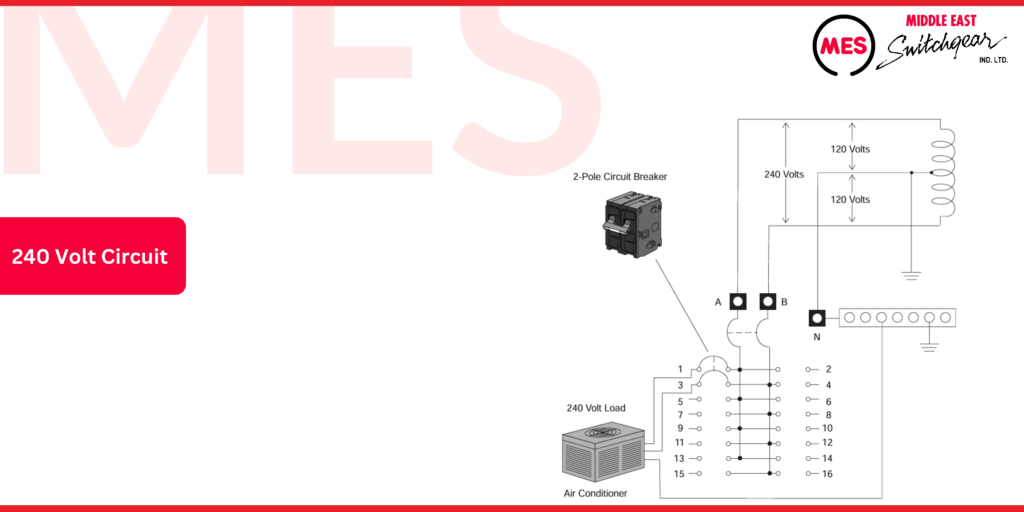
240 Volt Circuit
A circuit requiring 240 volts, such as an air conditioner or water heater, is connected through a 2-pole circuit breaker. In the following example, a 2-pole circuit breaker has been installed in positions 1 and 3. An air conditioner receives 240 volts from phase A, through the circuit breaker pole connected to position 1, and phase B, the pole of the circuit breaker connected to position 3. This leaves 4 circuit breaker positions for additional circuits.
Determining the Number of Circuits
In the following example, the number of circuits (spaces) required for a load center will be calculated using the same example to determine the load center current rating.
General Lighting Circuits
When determining the minimum number of lighting circuits for general lighting in a home, start by calculating the total load. For instance, if the general lighting load is 6000 VA, you can find the current by dividing the load by the maximum voltage. In most cases, the maximum voltage for general lighting is 120 volts.
To illustrate:
Current Calculation:
6000 VA ÷ 120 V = 50 A
You have the option to use either 15-amp or 20-amp circuit breakers, both with appropriately sized wiring. Typically, 15-amp circuit breakers are favored for general lighting applications.
To find the minimum number of circuits required, divide the total current by the size of the circuit breaker used. If opting for 15-amp breakers, the calculation would be as follows:
50 A ÷ 15 A = 4 circuits (rounded up from 3.33 to 4).
This means that at least four circuits are needed to handle the lighting load efficiently. Depending on the layout of the lighting fixtures and electrical receptacles, an electrician might recommend more than the minimum number of circuits to ensure optimal functionality and safety.
By following these guidelines, you can ensure your home’s lighting system is both effective and compliant with electrical standards.
Small Appliance Circuits
For a household with three 20-volt, 20-amp small appliance loads, you will need to install three 20-amp circuit breakers. This configuration ensures that each small appliance has its dedicated circuit, allowing for safe and efficient operation while adhering to electrical code requirements. Providing separate breakers helps prevent overloads and ensures that if one circuit trips, it won’t affect the others.
Laundry Circuits
In your electrical system, a 20-volt, 20-amp laundry circuit requires the installation of one 20-amp circuit breaker. This dedicated breaker ensures safe operation for the laundry appliances, complying with electrical standards and preventing potential overloads.
Air Conditioner Circuit
Large appliances must be evaluated individually to ensure proper electrical configurations. Appliances such as the air conditioner, heater, clothes dryer, and range typically operate on a 240-volt supply. Each of these appliances requires a 2-pole circuit breaker, which occupies two positions within the load center.
To determine the amperage for these appliances, divide their VA rating by 240 volts. For example, the air conditioner, rated at 9600 VA, calculates as follows:
9600 VA ÷ 240 V = 40 A
In selecting a circuit breaker, the ampere rating is generally set at 125% of the continuous load current. This approach aligns the wire size with the load capacity, promoting safety and efficiency. For the air conditioner, the calculation is:
40 A × 1.25 = 50 A
A 50-amp circuit breaker and 50-amp wiring are recommended to ensure reliable operation and compliance with electrical standards.
Electric Heater Circuit
The electric heater is a 240-volt, 50-amp device, calculated as:
12,000 VA ÷ 240 V = 50 A
To ensure safety, the circuit breaker must be rated at 125% of the continuous load:
50 A × 1.25 = 62.5 A
Since circuit breaker ratings must not exceed the conductor’s ampacity, wiring capable of handling 70 amps should be used. A 70-amp breaker—the next standard size above 60 amps—should be installed for this configuration.
Cloths Dryer Circuit
The clothes dryer operates on a 240-volt supply and has a 21-amp load, calculated as:
5000 VA ÷ 240 V = 21 A
To ensure safety, the circuit breaker rating must be 125% of the continuous load:
21 A × 1.25 = 26.25 A
In this case, 30-amp wiring and a 30-amp circuit breaker should be installed to meet electrical standards.
Electric Range Circuit
The electric range operates on a 240-volt supply with a load of 40 amps, calculated as:
9600 VA ÷ 240 V = 40 A
To ensure safe operation, the circuit breaker rating is set at 125% of the continuous load:
40 A × 1.25 = 50 A
For this setup, 50-amp wiring and a 50-amp circuit breaker are recommended to meet electrical code requirements.
Dishwasher Circuit
The dishwasher and garbage disposal operate on 120-volt circuits. The dishwasher, rated at 500 VA, has the following amperage:
500 VA ÷ 120 V = 4.2 A
To ensure safety, the circuit breaker size should be set at 125% of the continuous load:
4.2 A × 1.25 = 5.25 A
Since this value rounds up, 20-amp wiring and a 20-amp circuit breaker are required to ensure compliance with electrical standards.
Dishwasher Circuit
The garbage disposal operates on a 120-volt circuit and is rated at 1176 VA. The amperage is calculated as:
1176 VA ÷ 120 V = 9.8 A
Applying the 125% safety margin:
9.8 A × 1.25 = 12.3 A
Therefore, 15-amp wiring and a 15-amp circuit breaker are recommended to ensure safe operation and compliance with electrical standards.
Total Number of Spaces
The total number of load center spaces required can now be determined. A minimum of 18 spaces is needed to accommodate the circuits safely. However, since load centers are typically chosen with extra breaker spaces to allow for future expansion, a 24-space load center would be ideal.
INSERRT TABLE HERE
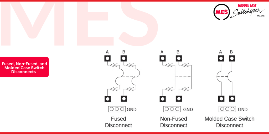
AC Disconnects
MES products feature a range of fused, non-fused, and molded case switch AC disconnects, designed to meet diverse electrical needs. These disconnects are housed in NEMA Type 3R enclosures, ensuring reliable performance in outdoor conditions. Customers can choose between steel or plastic enclosures based on their application requirements.
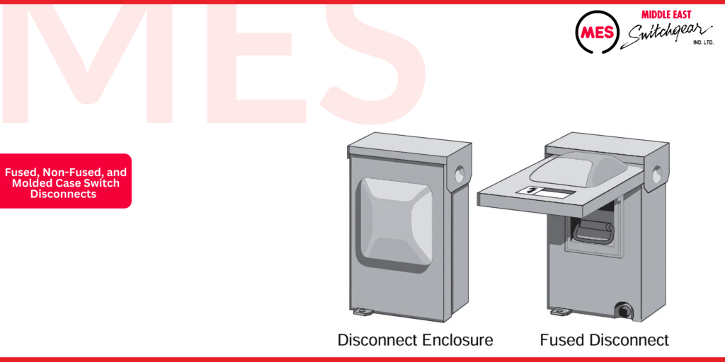
MES fused pullouts are rated for 240 volts, 2-pole, with options of 30 or 60 amps. Non-fused pullouts offer a 240-volt, 2-pole, 60-amp configuration. For added flexibility, molded case switch disconnects are available in 240 volts, 2-pole, with 50 or 60-amp ratings. These molded case switch disconnects come equipped with non-automatic QP molded case switch circuit breakers, ensuring secure and reliable performance.
Residential Metering
For many years, power companies have relied on watt-hour meters to measure electricity consumption for billing purposes. MES offers a wide range of metering enclosures designed to meet virtually every residential metering requirement. While MES also provides solutions for commercial and industrial applications, the focus here is on the most common types of residential metering enclosures.
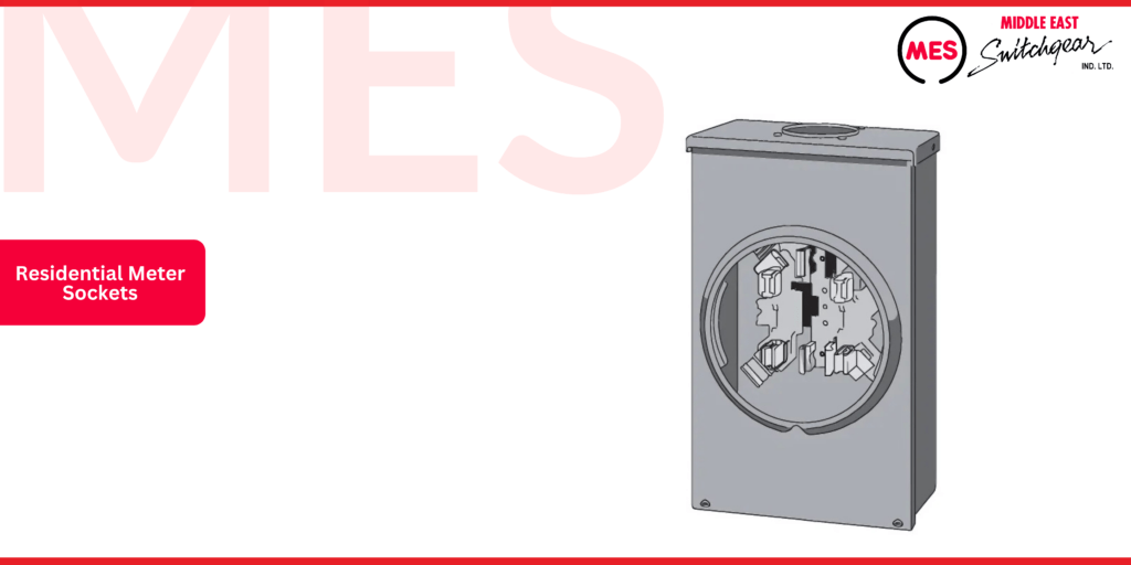
Residential Meter Sockets
Single-position meter sockets are ideal for single-family homes and are also used in some commercial settings. Multiple-position meter sockets, commonly referred to as gang sockets, are suited for multifamily buildings and commercial applications that require two to six meters.
These meter sockets support a maximum voltage rating of 600 volts and continuous current ratings of up to 320 amps per socket. Their design and performance comply with ANSI standard C12.7 and UL standard 414, ensuring reliable operation and safety.
Meter Combos
MES Meter Combos feature two primary product families: Meter Mains and Meter Load Center Combinations. Each of these families is further categorized into EUSERC Approved and Non-EUSERC Products, ensuring you have options that meet industry standards and specific installation requirements.
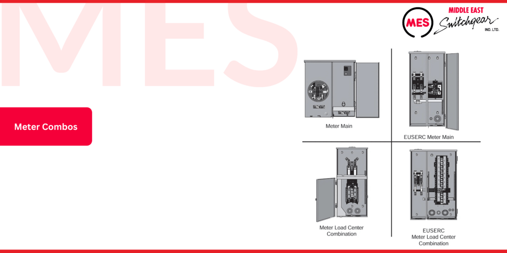
All MES products are UL-listed and suitable for use as service entrance equipment, featuring padlocking provisions for added security. The continuous current ratings for all four categories of Siemens meter combos range from 100 to 400 amps, while meter load center combinations range from 25 to 400 amps.
The Equipment Utility Service Requirements Committee (EUSERC) comprises approximately 80 utilities across 12 western states. One of EUSERC’s key functions is to specify manufacturing and installation requirements for metering and service equipment. Utility companies determine when EUSERC-conforming equipment must be utilized. However, EUSERC equipment can also be employed in areas where utility requirements do not mandate it.
Meter Mains
A meter main combines a meter socket with a main circuit breaker in a single enclosure. This configuration is often required by utilities as it places the main breaker outside the residence, allowing service personnel to disconnect power more easily.
When selecting a meter main, all the essential information needed for a meter socket is also applicable. This includes:
- Amperage rating
- Ring type
- Bypass type
- Service conductor feed (whether underground or overhead)
- Number of jaws
Additionally, you’ll need to consider the frame type, continuous current rating, and interrupting rating for the circuit breakers.
Meter Load Center Combinations
A meter load center combination integrates a meter socket with a main breaker and load center into one unit. However, if only six or fewer branch circuit breakers are necessary, the National Electrical Code (NEC®) does not mandate a main breaker.
These combinations are becoming increasingly popular as they provide a centralized location for the meter socket, main breaker, and load center. This convenience allows contractors to save on both labor and material costs, streamlining the installation process.
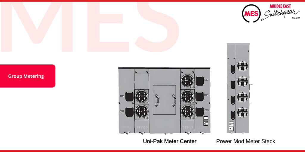
Group Metering
Uni-Pak meter centers provide an effective solution for multi-family dwellings. These self-contained systems feature two to six-meter compartments, ensuring efficient metering for individual units. Each tenant has their branch circuit breakers located in a separate compartment adjacent to the meter socket, promoting organization and accessibility.
Additionally, Power Mod modular metering offers a versatile range of module types that can be easily configured to accommodate a variety of residential and commercial group metering applications. For instance, a typical setup may include a main device module paired with one or more residential or commercial meter stacks, providing a comprehensive metering solution.
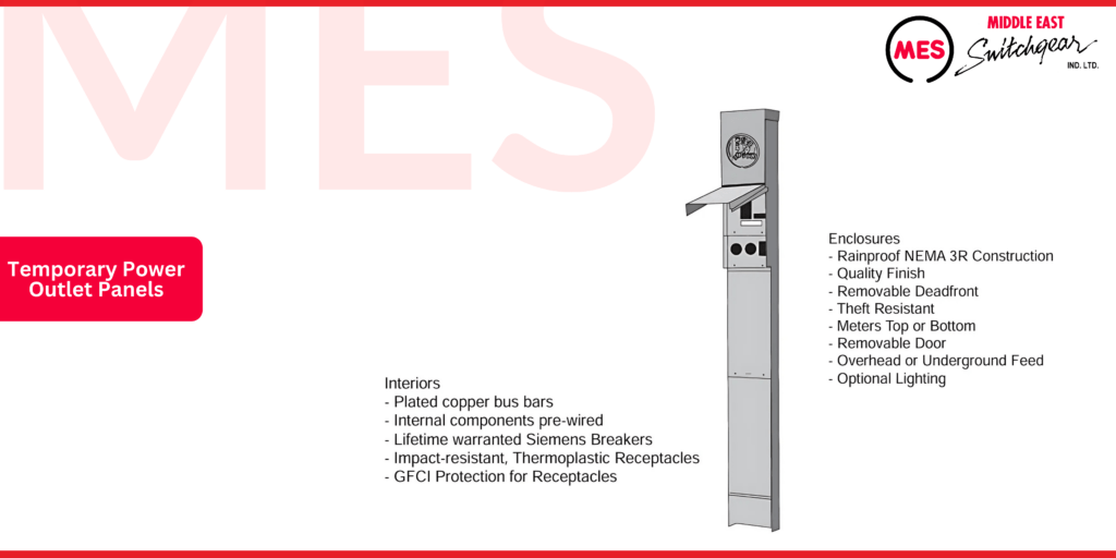
Temporary Power Outlet Panels
As the demand for accessible electrical power increases—driven by the growth of homes and the popularity of recreational vehicles (RVs)—having reliable power outlets becomes essential. To address the electrical needs of temporary service and comply with NEC® standards, a safe and dependable power outlet is necessary.
MES All-Sites temporary outlet panels offer a range of options for UL-listed power outlets, ideal for use as temporary service equipment during construction or as power supply panels for RVs. These panels are designed for flexibility, available in single-panel or back-to-back configurations, and can be mounted on the surface earth-mounted or pad-mounted pedestals.
Both unmetered and metered versions, including ring type and ringless configurations, are available in all options, ensuring you have the right solution for your temporary power needs.