Table of Contents
Distribution Systems
Power distribution systems are used in every residential, commercial, and industrial building to control electrical power distribution throughout the facility safely.
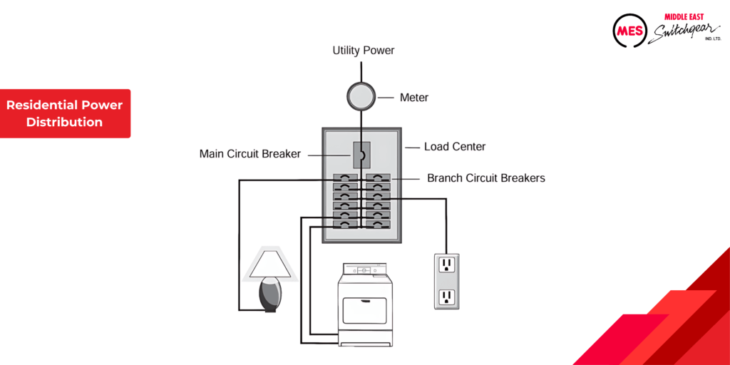
Residential Power Distribution
Many are familiar with the residential power distribution system found in average homes. Electricity purchased from a utility company enters through a metering device. It is then distributed by a load center to various branch circuits, serving lighting, appliances, and electrical outlets.
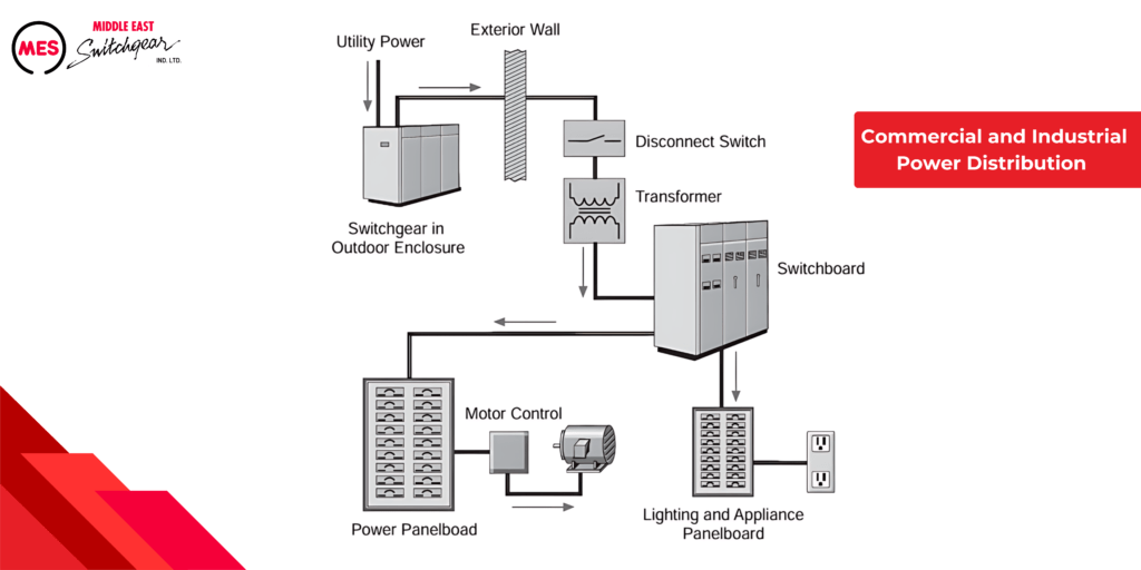
Commercial & Industrial Power Distribution
Power distribution systems in multi-family, commercial, and industrial facilities are notably intricate. These systems typically include metering devices for power measurement, main and branch disconnects, protective devices, and switching mechanisms to regulate power flow. Conductors and transformers facilitate distribution through switchboards, transformers, and panelboards.
Effective distribution systems result from meticulous engineering. They ensure safe and efficient electric service for current demands while accommodating potential future expansions.
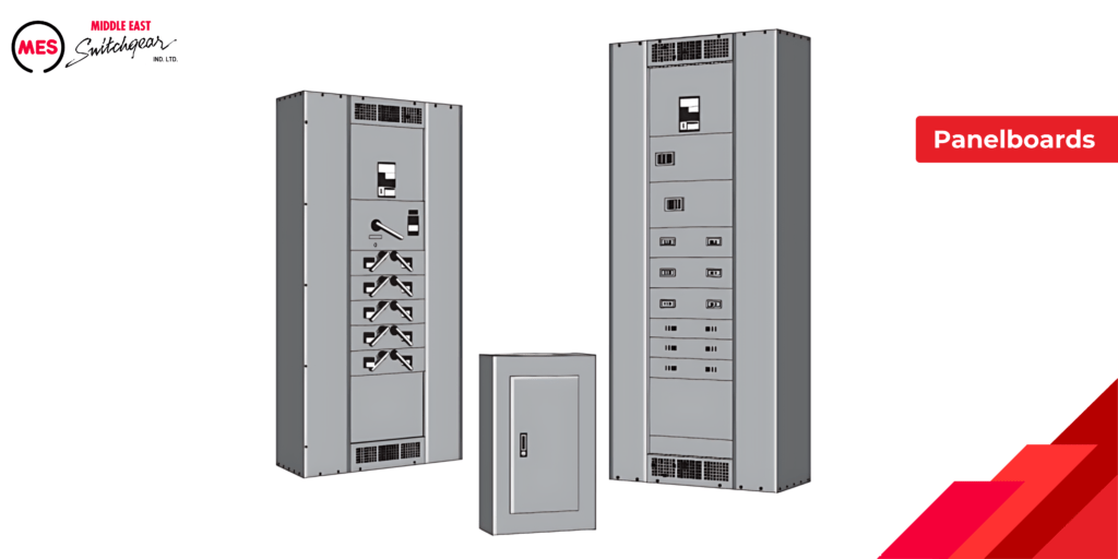
Panelboards
Electrical distribution systems, ranging from straightforward to intricate, invariably feature panelboards, which are central to this course’s focus. Even the load center found in residential settings qualifies as a type of panelboard. However, the emphasis of this course centers on panelboards utilized specifically in commercial and industrial environments.
Panelboard Definition
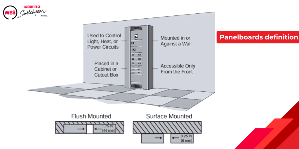
A panelboard serves as an enclosure for overcurrent protection devices, along with the buses and connections that distribute power to these devices and their associated circuits. According to the National Electrical Code® (NEC®), a panelboard is specifically designed for:
- Controlling light, heat, or power circuits
- Installation in a cabinet or cutout box
- Mounting in or against a wall
- Accessibility exclusively from the front
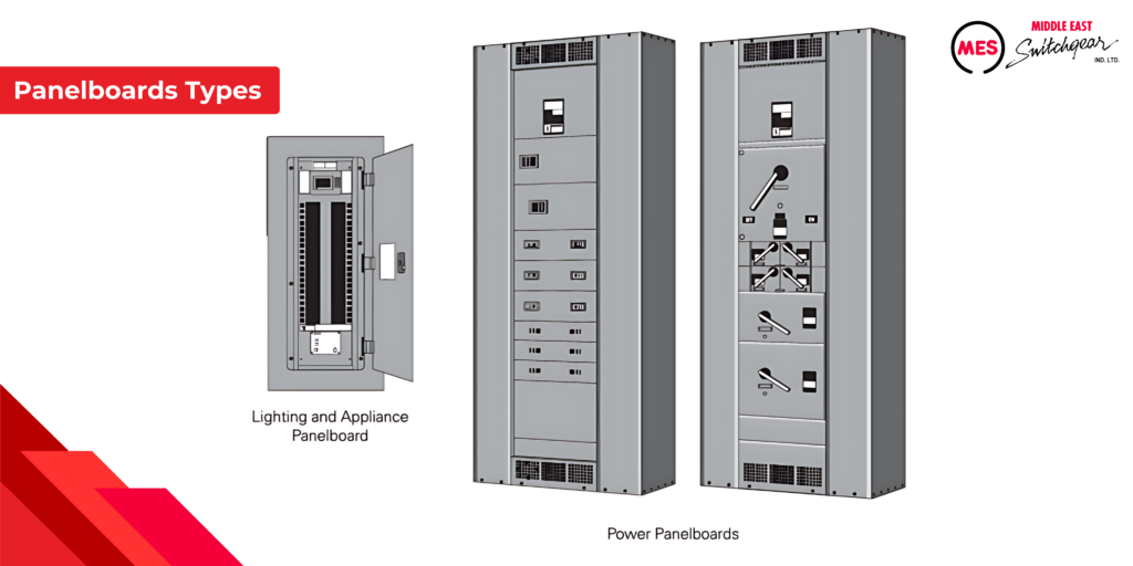
Panelboards are frequently divided into two categories:
• Lighting and appliance branch-circuit panelboards
• Power panelboards (also called distribution panelboards)
Before the 2008 National Electrical Code® (NEC®), distinctions between panelboard types were outlined in NEC® Articles 408.34 and 408.35. These articles imposed specific regulations on lighting and appliance panelboards, stipulating that those not meeting these criteria were classified as power panelboards.
For instance, a lighting and appliance branch-circuit panelboard required more than ten percent of its overcurrent protection devices (excluding main devices) to safeguard lighting and appliance circuits. A lighting and appliance branch circuit includes connections to the panelboard neutral with overcurrent protection devices rated at 30 amps or less. Each pole of a device counted as one device under this definition. Moreover, a lighting and appliance panelboard could house a maximum of 42 overcurrent protection devices (poles) within a single cabinet or cutout box.
Articles 408.34 and 408.35, along with their corresponding restrictions, were eliminated from subsequent editions of the National Electrical Code® starting from the 2008 version. Nevertheless, terms like ‘lighting and appliance panelboard’ (also known as a lighting panel) and ‘power panelboard’ (also referred to as a power panel or distribution panelboard) continue to be widely used.
Overcurrent Protection Devices
Conductors always generate heat when current flows through them, and higher currents generate more heat. Excessive heat can be harmful to electrical conductors. Therefore, conductors are assigned a continuous current carrying capacity, known as ampacity. When current exceeds this rated capacity, it causes overcurrent. Overcurrent can occur due to short circuits, overloads, or ground faults.
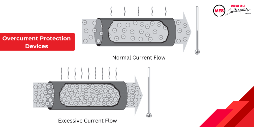
A short circuit happens when two bare conductors make contact, drastically reducing the resistance between them. This sudden drop in resistance leads to a rapid and destructive increase in current. In contrast, an overload involves a current that is typically lower than in a short circuit. It occurs when a circuit is overloaded with too many devices or when electrical equipment operates beyond its rated capacity. Lastly, a ground fault occurs when a current unexpectedly flows to the ground through an unintended path. The severity of a ground fault depends on the path’s resistance and the applied voltage.
Overcurrent protection devices safeguard conductors from excessive current flow. These devices vary in their capabilities: some protect against short circuits only, others handle both short circuits and overloads, and some cover all types of overcurrents.
Ideally, overcurrents wouldn’t occur, but when they do, these protection devices automatically disconnect electrical equipment from the power source. They must accurately distinguish between a minor overcurrent and a short circuit, responding appropriately. Minor overcurrents may be tolerated briefly, but as current levels rise, the device must react swiftly. Short circuits necessitate immediate interruption
Fuse
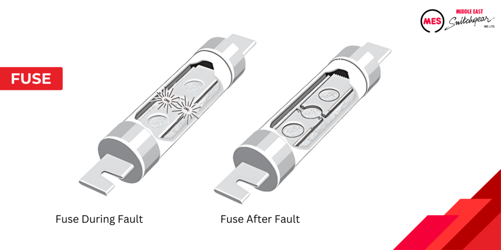
A fuse serves as a type of overcurrent protection device known for its one-shot operation. When subjected to overcurrent, the fuse’s current-carrying element heats up, melting and opening the circuit to disconnect the load from the power source.
Non-Time-Delay Fuses
A fuse represents a crucial type of overcurrent protection device, notable for its one-shot functionality. When exposed to excessive current, the fuse’s internal element heats up, triggering it to melt and open the circuit. This action effectively disconnects the load from the power source, safeguarding electrical equipment from damage.
Time-delay Fuses
Time-delay fuses serve a critical role in providing protection against both overload and short circuits. Specifically designed for motor applications, these fuses are engineered to tolerate currents several times higher than their rated capacity for a brief period. This feature ensures motors can start smoothly without prematurely blowing the fuse.
Fuse Classes
Underwriters Laboratories (UL) plays a pivotal role in establishing and standardizing the fundamental performance and physical specifications for products undergoing safety testing. Among UL’s standards are those governing classes of low voltage fuses, applicable to fuses with voltage ratings of 600 volts or less. The table below highlights the most prevalent fuse classes typically found in panelboards.
Fuses are categorized into classes according to their operational and constructional features. Each class is assigned an interrupting rating, which denotes the maximum current the fuse can safely interrupt. Fuses also come with maximum continuous current and voltage ratings.
When choosing fuses, it’s essential to consult the manufacturer’s application data to ensure compatibility with the specific load types involved.
Fusible Disconnect Switch
A fusible disconnect switch is a crucial device used in panelboards to offer overcurrent protection. Fuses integrated within the switch are carefully chosen to match specified current and voltage levels, ensuring they provide the necessary interrupting rating.
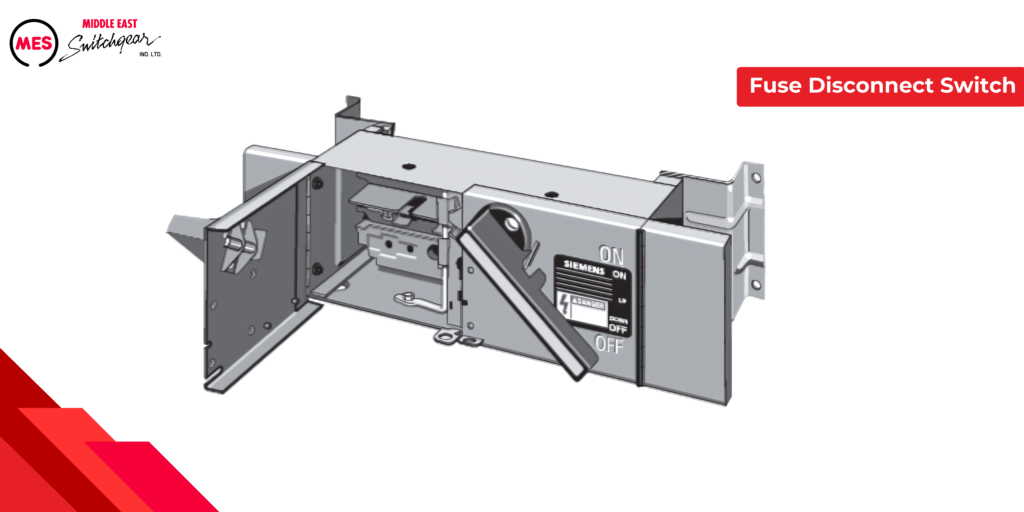
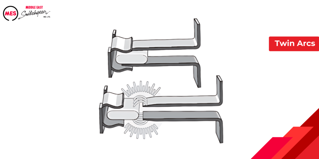
Our Vacu-Break fusible switches, available up to 600 A, utilize Clampmatic technology to securely grip current-carrying contact surfaces, minimizing heat buildup. When switched OFF, the movable contact swiftly snaps away from the jaws, ensuring a rapid and clean break. This design also produces twin arcs that are smaller and extinguish faster compared to single arcs found in other switch designs.
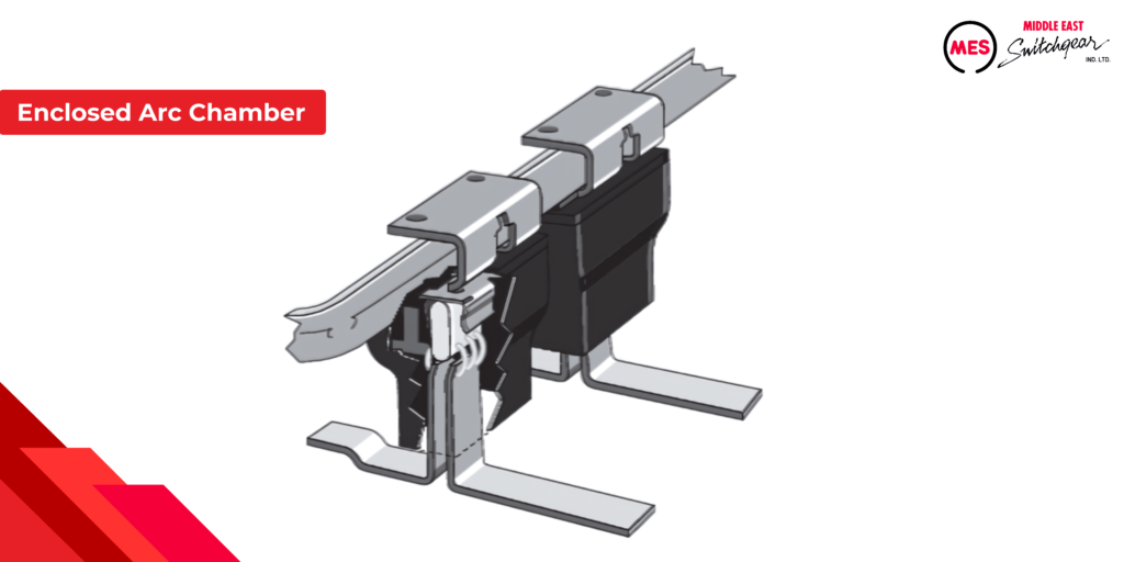
The contacts are surrounded by an enclosed arc chamber which absorbs much of the heat from the arching. The enclosed chamber limits oxygen to more rapidly cool and extinguish arcs.
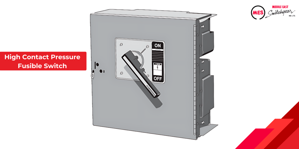
High Contact Pressure Fusible Switches
Our high contact pressure (HCP) fusible switches have continuous current ratings from 400 A to 1200 A.
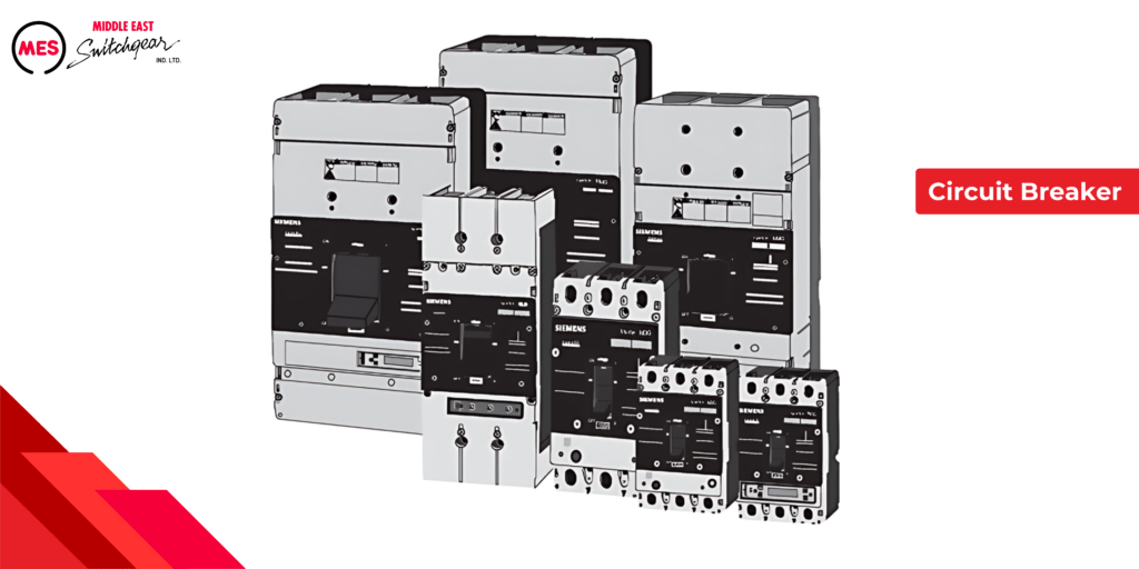
Circuit Breaker
Another essential device for overcurrent protection is a circuit breaker. While some circuit breakers may incorporate fuses, the majority do not. Similar to a fusible switch, a circuit breaker offers reliable overcurrent protection and allows manual control over power distribution.
When an overcurrent occurs, the circuit breaker automatically trips to disconnect power from the circuit. The speed of the trip depends on the severity of the overcurrent. Once the overcurrent issue is resolved, resetting the circuit breaker is as simple as flipping its operating handle.
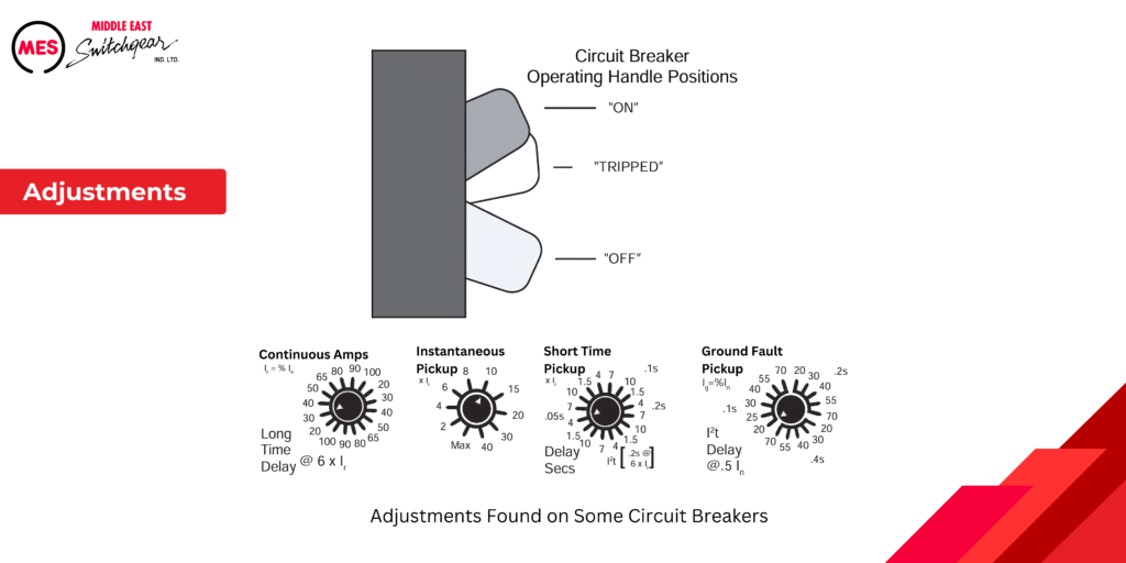
One of the primary advantages of circuit breakers is their ability to restore a circuit without needing a replacement fuse. Additionally, circuit breakers offer other benefits. Some models feature adjustable settings or replaceable trip units to match specific fault current levels required for different applications. Advanced circuit breakers may also include communication capabilities for sending data to power monitoring equipment or display devices.
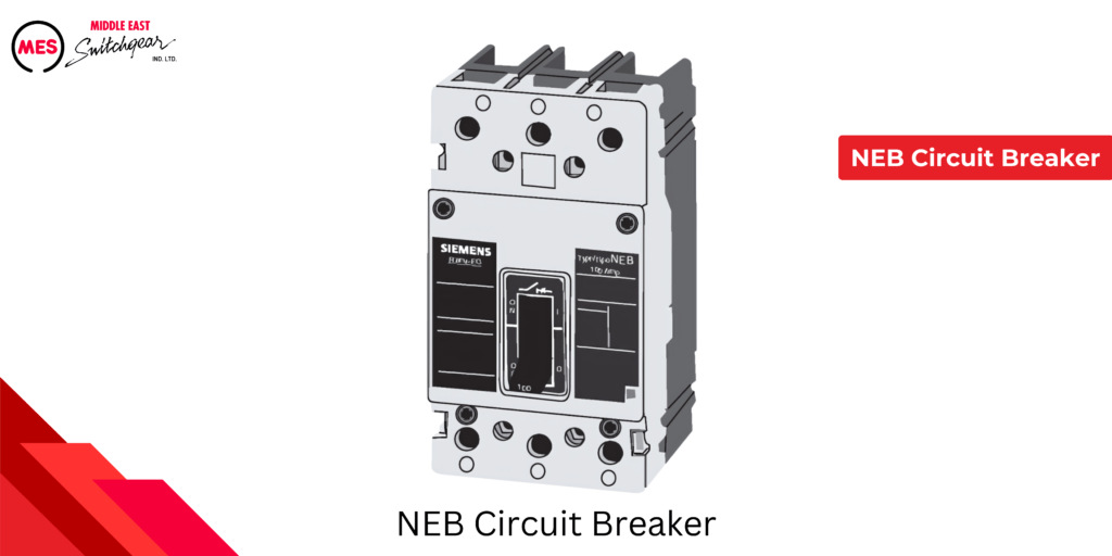
Circuit Breaker Voltage Rating
The rated current for a circuit breaker is typically denoted as In, as illustrated in the chart below for an NEB circuit breaker. It’s important not to confuse this with the current setting (Ir), which applies to circuit breakers equipped with a continuous current adjustment. Ir represents the maximum continuous current that the circuit breaker can carry without tripping at the specified setting. This value may be expressed in amperes (amps) or as a percentage of In.
Circuit Breaker Continuos Rating
Conductors have a specified capacity for carrying continuous current, known as their ampacity. Generally, the ampere rating of a circuit breaker and the ampacity of connected conductors must meet or exceed the sum of noncontinuous load current plus 125% of continuous load current.
MES circuit breakers are rated based on the use of 60°C or 75°C conductors. This means that even if a conductor has a higher temperature rating, its ampacity must be calculated based on its 60°C or 75°C rating.
Circuit Breaker Frame Size
The circuit breaker frame encompasses all components of the breaker, excluding the trip unit. Within a single frame size, circuit breakers of various current ratings can be produced by installing different trip units. The frame size denotes the highest continuous current rating achievable with a specific breaker frame.

Circuit Breaker Interrupting Rating
Circuit breakers are rated based on their ability to interrupt maximum current levels, known as the interrupting rating or ampere interrupting rating (AIR). Separate UL and IEC standards govern these ratings due to differing testing specifications.
When designing a power distribution system, it’s crucial to select a main circuit breaker capable of interrupting the highest potential fault current expected in the application. Branch circuit breakers also require careful consideration of their interrupting ratings, which may vary depending on the feasibility of series ratings.
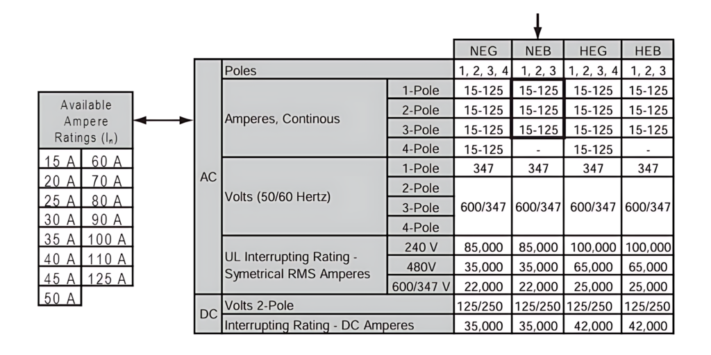
The interrupting ratings of a circuit breaker are typically expressed in symmetrical RMS amperes for specific rated voltages. RMS, or root-mean-square, denotes the effective value of an alternating current or voltage. The term ‘symmetrical’ indicates that the specified alternating current value is balanced around zero, featuring equal positive and negative half cycles. MES circuit breakers offer interrupting ratings ranging from 10,000 to 200,000 amps.
Below is a table displaying the UL interrupting ratings for type NEB circuit breakers. For ratings of other MES circuit breakers, consult the SPEEDFAX catalog, available in both print and online versions on the our website.
Panelboard Construction
Panelboards come in various sizes and constructions, but they share common components. Each panelboard includes a can, interior, circuit protection devices, label, and trim.
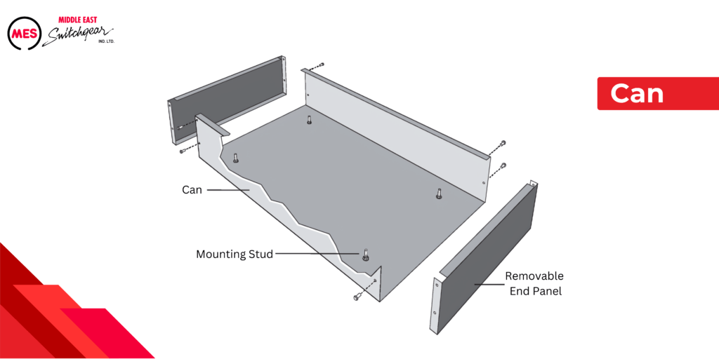
Can
Typically made of galvanized steel, the can serves as the enclosure housing all other components. Also known as a box or enclosure, it ensures both component and personnel protection. Users can customize conduit holes with removable blank end panels, while pre-stamped knockouts are available as an alternative. Mounting studs support the interior or grouped devices.
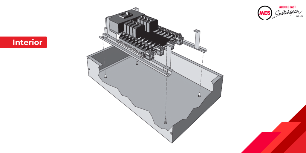
Interior
The interior of a panelboard comprises essential components such as overcurrent protection devices, bus bars, and insulated neutral bus bars. In a lighting panel, the interior is secured to the four mounting studs within the can, allowing for adjustments using jacking screws (not depicted).
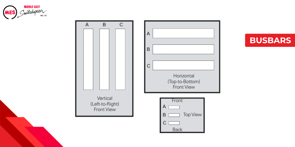
Busbars
A bus bar functions as a conductor that connects multiple circuits. In MES panelboards, standard bus bars are crafted from aluminum, though copper alternatives are also offered.
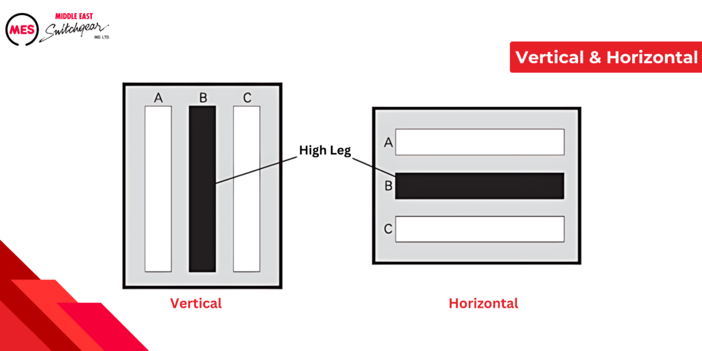
According to NEC® Article 408, three-phase panelboard bus bars must arrange phases sequentially, as illustrated in the diagram below. This ensures consistent phase alignment across all termination points within a panelboard or switchboard. The article does provide exceptions to this rule; for further information, refer directly to NEC® Article 408.
High Leg
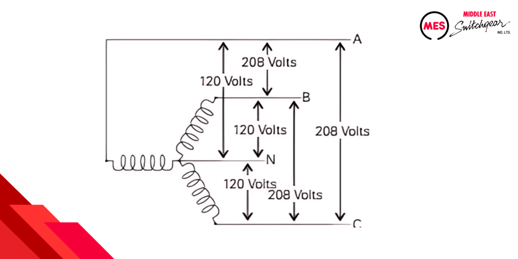
Some power supply systems utilize a transformer featuring a three-phase, four-wire (3Ø4W) delta-connected secondary with a grounded center-tap connection on one phase. The diagram below illustrates such a system, where each phase-to-phase voltage measures 240 volts. One phase winding midpoint is grounded to yield 120 volts between phase A and neutral, and 120 volts between phase C and neutral. However, phase B to neutral measures 208 volts, known as the high leg.
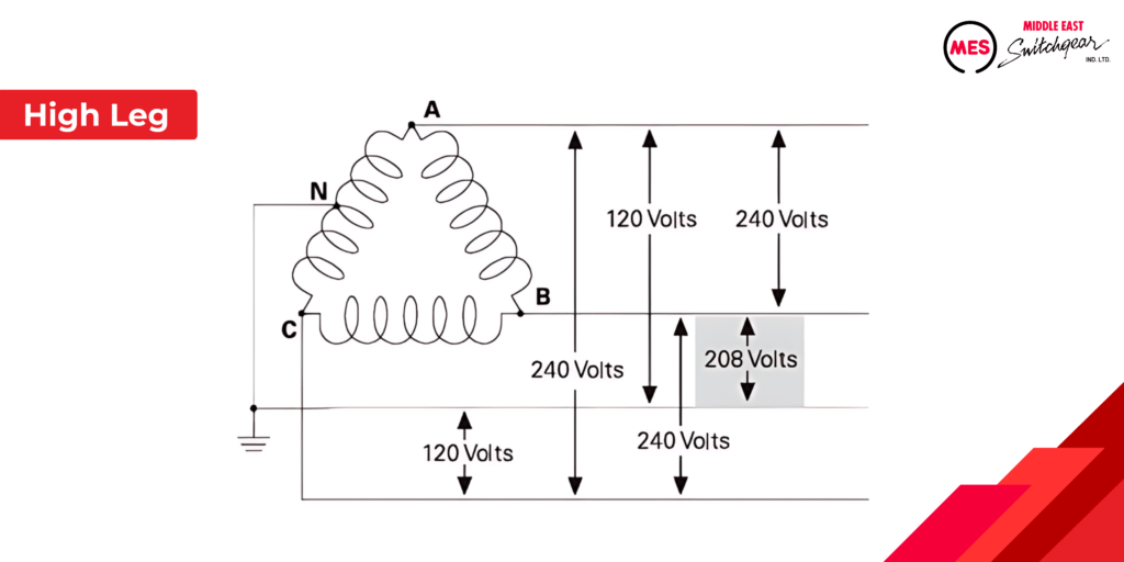
According to NEC® Article 110.15, the high leg conductor or bus bar must be permanently marked with an orange finish “or by other effective means.” Additionally, NEC® Article 408.3 specifies that the B phase should serve as the high leg. Alternate bus bar arrangements are acceptable for existing installations but require appropriate marking. Further details on calculating the high leg value and connecting loads will be covered later in this course.
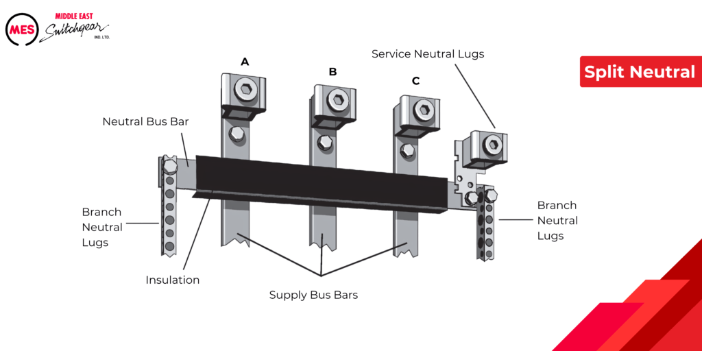
Split Neutral
MES panelboards are equipped with a split neutral design, allowing neutral connections on both sides of the panelboard. This configuration utilizes an insulated neutral bus bar to facilitate the split neutral connections.
200% Neutral
Certain loads can induce harmonics and non-linear loading on your distribution system, necessitating careful selection of a panelboard. One effective solution for handling non-linear loads involves doubling the panelboard’s neutral capacity. Our panelboards offer the option of a 200% neutral capacity to address this requirement.
Circuit Protection Devices
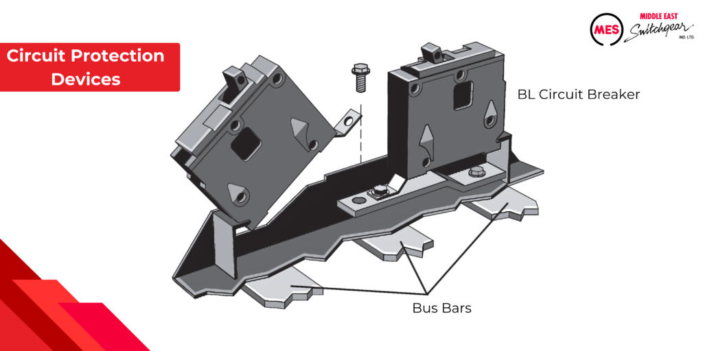
While it is common for load centers to have plug-in branch circuit breakers, circuit breakers used in panelboards for commercial and industrial applications typically bolt onto the bus bars. For example, the following illustration shows two BL circuit breakers, one is mounted to the panelboard bus and the other is being mounted.
Circuit Identification
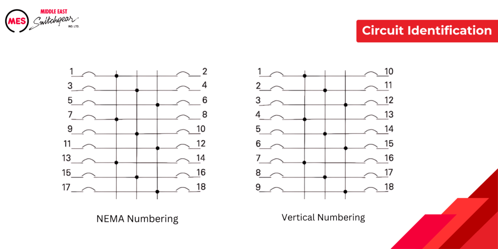
Specifications often mandate that panelboard circuit terminals are clearly labeled or accompanied by a wiring diagram. A common method for numbering terminals involves assigning odd numbers to poles on the panelboard’s right side (your left when facing it) and even numbers on the left side, a practice known as NEMA numbering. In certain cases, specifications may also call for vertical numbering.
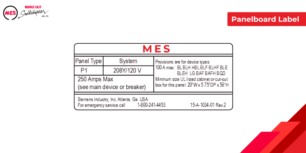
Panelboard Label
The label identifies the panelboard’s type, voltage rating, and ampacity.
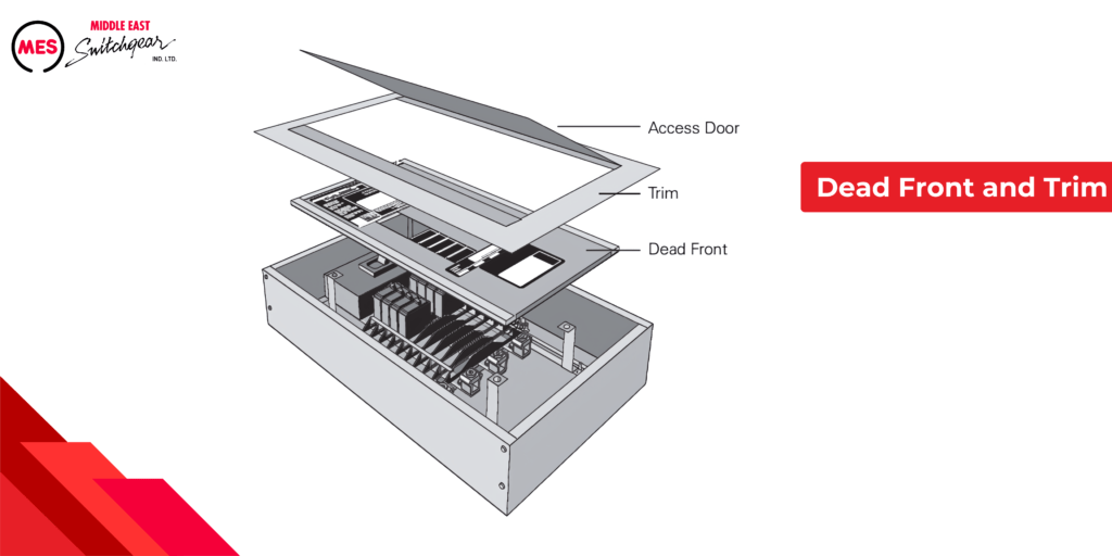
Dead Front and Trim
The dead front and trim of a panelboard encompass its front surfaces, which enclose the interior components. The trim features an access door, allowing entry to the overcurrent devices while effectively sealing off the bus bars and internal wiring, preventing inadvertent contact.
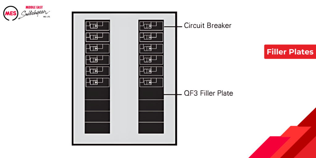
Filler Plates
QF3 filler plates are used to cover any unused pole spaces not filled by a circuit breaker.
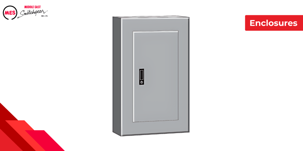
Enclosures
The National Electrical Manufacturers Association (NEMA) sets standards for electrical equipment enclosures. MES panelboards are supplied as standard in a NEMA Type 1 enclosure, designed for general-purpose indoor use.
The following enclosures are available as an option:
Type 3R:
Enclosures are primarily intended for outdoor use to offer protection against rain, sleet, and external ice formation.
Type 4X:
Enclosures are designed for both indoor and outdoor applications to protect against corrosion, windblown dust, rain, splashing water, hose-directed water, and damage from external ice formation.
Type 3R/12:
Enclosures are primarily designed for indoor use to offer protection against circulating dust, falling dirt, and dripping noncorrosive liquids.
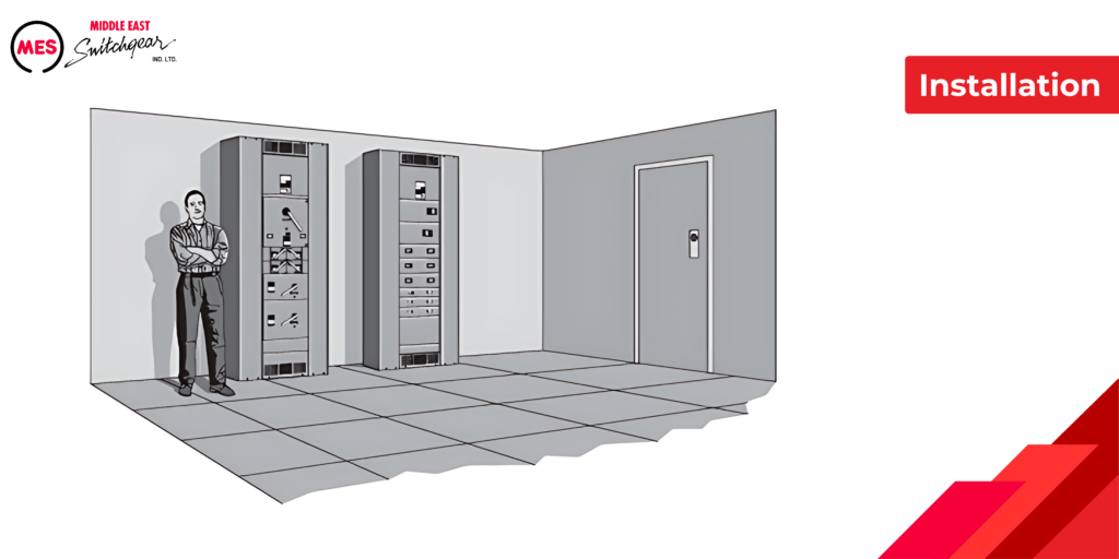
Installation
Installing a panelboard requires meticulous planning to ensure a safe environment for personnel and equipment. According to Article 110.26 of the NEC®, this regulation addresses clearances around electrical equipment, including panelboards.
The purpose of Article 110.26 is to establish adequate space for personnel to inspect, adjust, service, and maintain energized equipment. It specifies dimensions for the depth, width, and height of this workspace.
Moreover, Article 110.26 outlines entry requirements into the workspace and mandates dedicated equipment space for both indoor and outdoor installations. For detailed guidelines on workspace requirements, consult this article.
Individual Overcurrent Protection
According to NEC® Article 408.36, panelboards must be safeguarded by an overcurrent protection device that does not exceed the panelboard’s rating.
There are two primary methods to achieve individual panelboard overcurrent protection, as illustrated below. The main overcurrent protection device, such as a circuit breaker, can either be integrated within the panelboard itself or situated on the supply side. For instance, both the main breaker and panelboard in this example are rated at 600 amps.
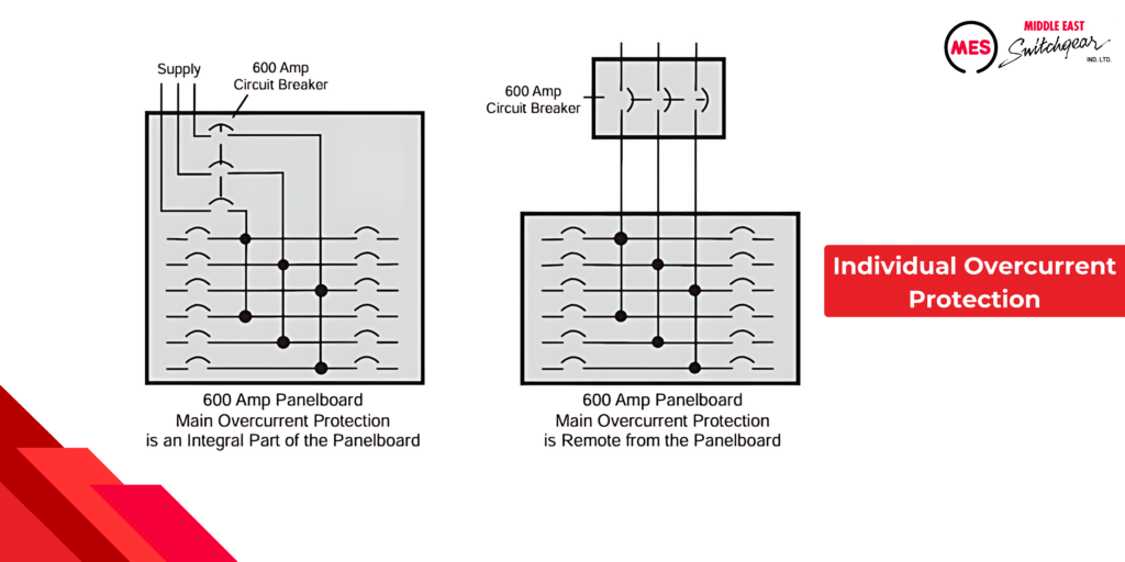
NEC® Article 408.36 does provide for exceptions to this rule. Refer to the complete article and NEC® Article 230.71 for additional details.
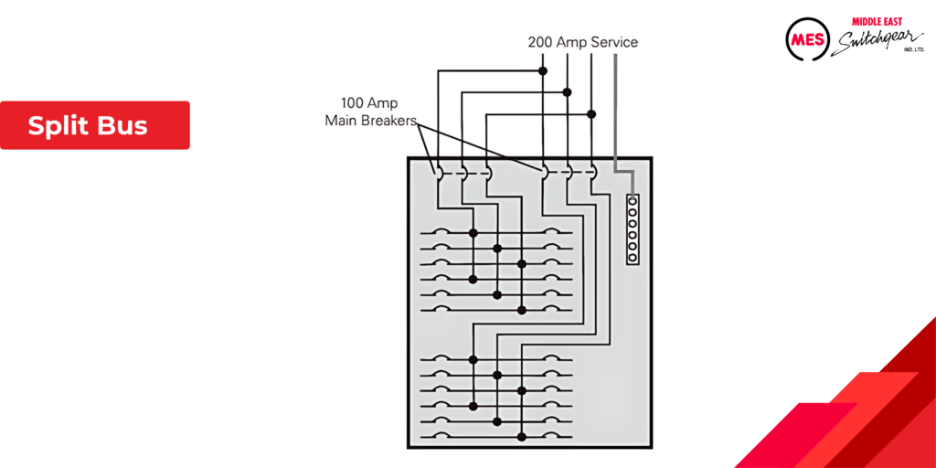
Split Bus
One exception outlined in NEC® Article 408.36 permits panelboards to be protected by either two main circuit breakers or two sets of fuses, provided their combined current rating does not exceed the panelboard’s rating. When employing two main circuit breakers in a panelboard, a split bus configuration is utilized. This setup divides the branch circuits, with one main circuit breaker protecting half of them and the other main circuit breaker protecting the remaining half. It’s important to ensure that the total rating of these circuit breakers does not exceed the panelboard’s specified rating.
Panelboard Supplied by a Transformer
Panelboards often receive power from a transformer’s secondary side. Per NEC® Article 408.36, individual protection for the panelboard is required on this secondary side of the transformer. The overcurrent protection device can be installed either upstream or within the panelboard itself.
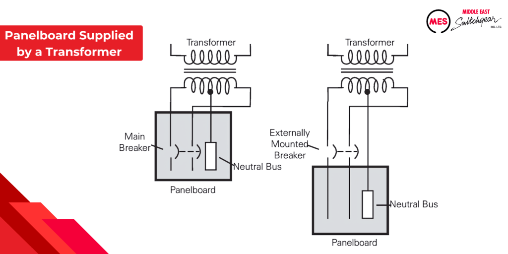
NEC® Article 408.36 (B) provides an exception to this rule. Refer to this article and Article 240.21 for additional details.
Panelboards Main Configurations
There are three main configurations for panelboards: main lug only, main breaker, and main switch (fusible switch). These configurations are available for power panels. Lighting panels, on the other hand, are typically offered in either main lug only or main breaker configurations.
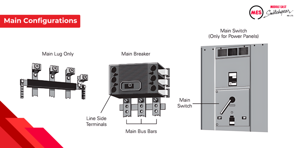
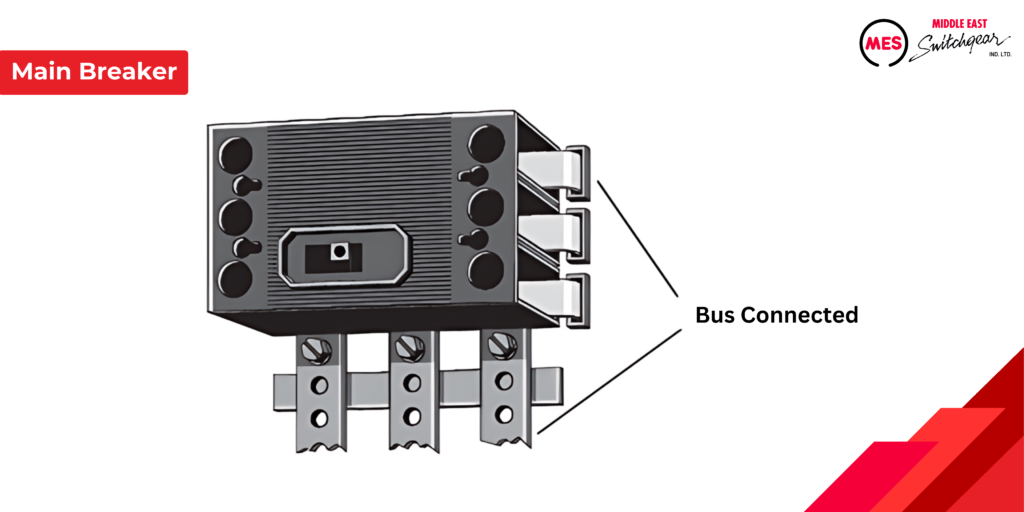
Main Breaker Panelboard
The incoming supply cables of a main breaker-type panelboard are connected to the line side of the main breaker. This main breaker then distributes power to the panelboard and its branch circuits. It serves to disconnect power from the panelboard and protects short circuits, overloads, and, if equipped, ground faults.
MES main breakers are bus-connected directly to the main bus bars. This eliminates the need for cable connections between the main circuit breaker and the lugs on the main bus bars. Bus connection enhances circuit integrity by minimizing the risk of loose connections that can cause overheating.
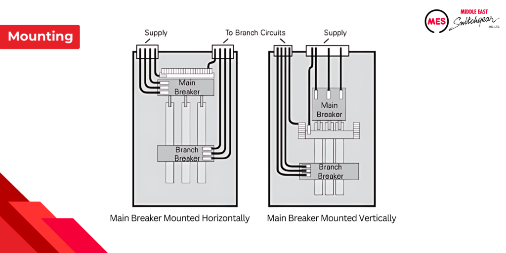
Depending on the panelboard, the main breaker can either be mounted horizontally or vertically.
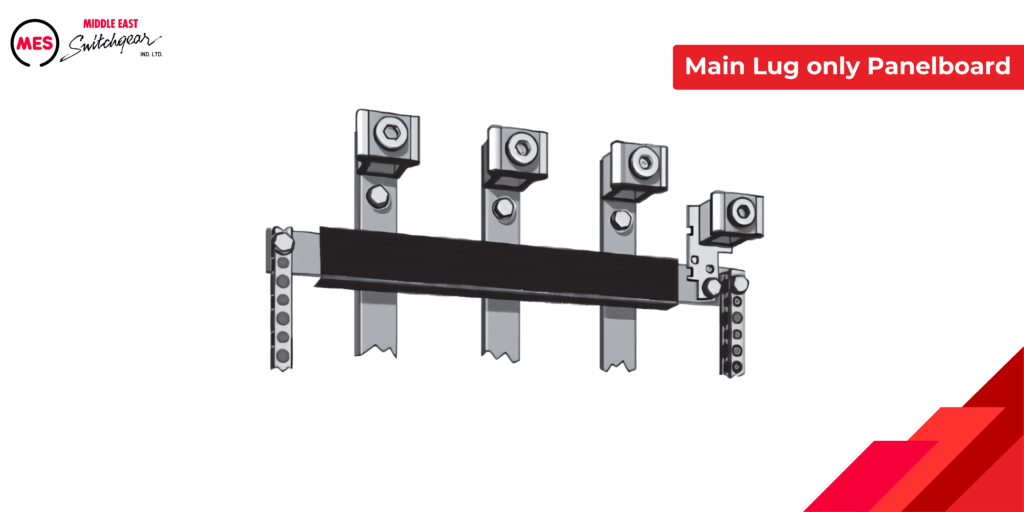
Main Lug Only Panelboard
A main lug-only type panelboard does not have a main circuit breaker. The incoming supply cables are connected directly to the bus bars. Primary overload protection for the panelboard is not provided as an integral part of the panelboard.
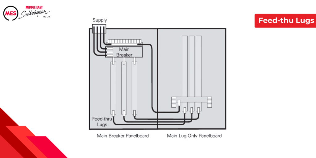
Feed-thu Lugs
In the realm of panel boards, understanding the versatile applications of main breaker and main lug-only configurations is crucial. For instance, the integration of feed-thru lugs, strategically placed opposite the main bus of a main breaker panel board. This setup facilitates seamless connection to a main lug-only panel board, illustrating the flexibility and utility inherent in panel board designs.
The feed-thru lugs, positioned on the main breaker panel board’s main bus, establish a direct connection to the main lug-only panel board. This configuration ensures that the main breaker provides essential overcurrent protection for both panel boards, guaranteeing safety and operational integrity.
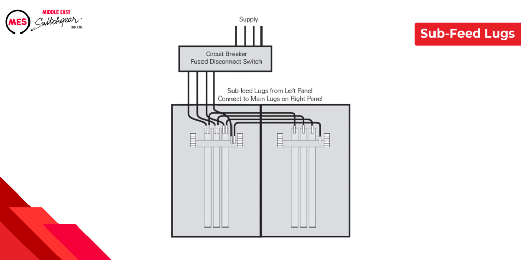
Sub-Feed Lugs
Sub-feed lugs are positioned adjacent to the main incoming lugs on a panel board, serving to link one or more additional panel boards to the same feeder. In the illustrated example, two neighboring main lug-only panel boards are connected to the feeder via a fusible switch or circuit breaker. The electrical power, regulated by the overcurrent protection device, flows to the left panel board directly and through the sub-feed lugs to the right panel board.
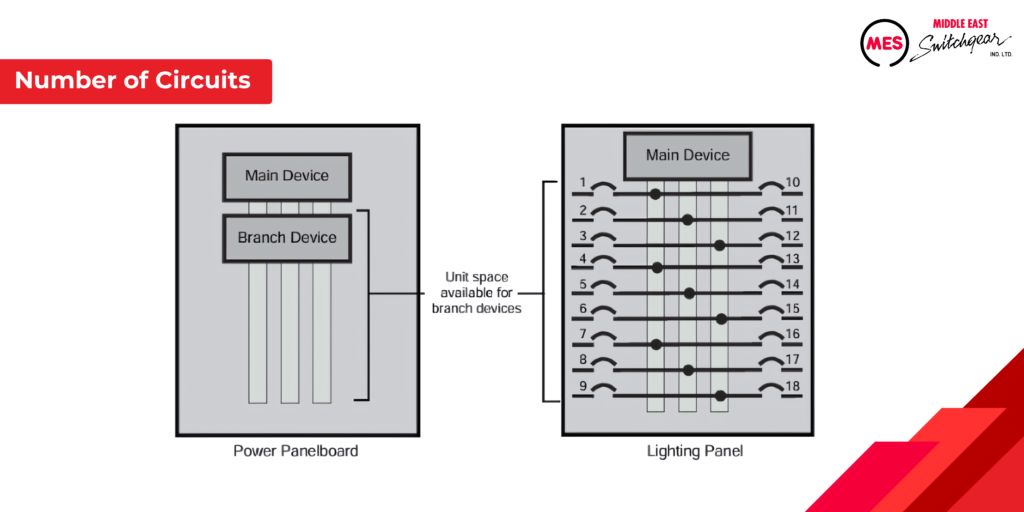
Unit Space and Number of Circuits
The mounting height of circuit breakers or fusible switches, often termed as unit space, plays a critical role in panel board configurations. The available unit space for installing branch devices depends on factors such as panel board type, enclosure dimensions, and the configuration of the main device. Due to the varying unit space requirements of circuit breakers and fusible switches, the capacity for mounting branch devices within a panel board can differ accordingly.
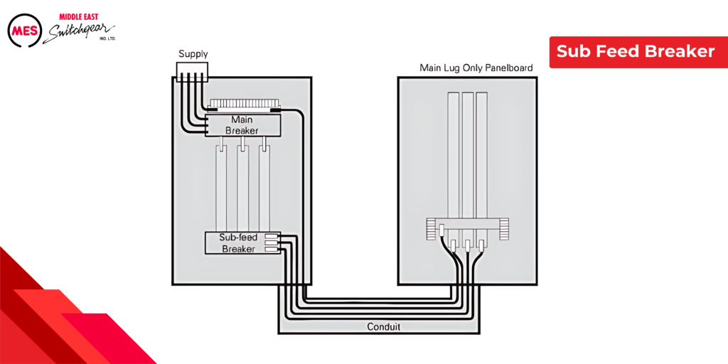
Sub-feed Breaker
When an application requires a circuit breaker that is a larger frame size than the branch circuit breakers available and will not fit in a branch circuit location, a sub-feed breaker can be used. One possible application is to supply a second panelboard located some distance from the first panelboard. However this is not the only application. A sub-feed breaker can supply any load that a branch circuit breaker can supply.
Power supply Systems
Panelboards are essential components in electrical systems, receiving power from various sources. Typically, a downstream panel board draws power from an upstream panel board or switchboard within a facility. However, the origin of the power for the entire distribution system lies with utility companies. This utility power is initially transformed down through transformers before being distributed to residential, commercial, or industrial facilities. Transformer secondary windings are configured in several ways to provide service, each affecting the choice of panel board. Understanding the specific voltage and system configuration is crucial for selecting the appropriate panel board. The examples below highlight common configurations, but numerous other systems and voltages are also prevalent.
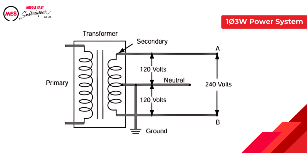
1Ø3W Power System
The following diagram illustrates a common single-phase, three-wire (1Ø3W) distribution system. As this diagram shows, the voltage between the neutral connection (N) of the transformer secondary and either side of the secondary is 120 V and the voltage across the entire secondary winding is 240 V.
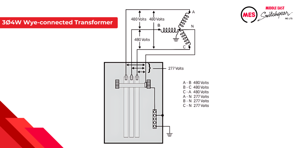
3Ø4W Wye-connected Transformer
The following illustration depicts the secondary side of a wye-connected transformer rated at 480Y/277 V three-phase, four-wire (3Ø4W) configuration. In this context, ‘480Y’ signifies the transformer’s wye connection and a phase-to-phase voltage of 480 volts. Meanwhile, ‘277 V’ denotes the voltage between any phase and neutral (N). Understanding the phase voltage in such systems allows the calculation of the phase-to-phase voltage by multiplying the phase-to-neutral voltage (277 V) by 1.732, resulting in approximately 480 V.
3Ø4W Delta-connected Transformer, BØ High Leg
A delta-connected secondary in a three-phase, four-wire (3Ø4W) configuration operates with unique characteristics. The accompanying illustration demonstrates a delta-connected secondary producing 240 V phase-to-phase. Grounding the midpoint of one phase winding allows for 120 V between phase A or C and the neutral connection. However, phase B to neutral measures 208 V, known as the high leg. Typically, in four-wire delta configurations, phase B serves as the high leg.
Calculating the high leg voltage involves multiplying the phase A (or C) to neutral voltage by 1.732 (120 V x 1.732 = 208 V). It’s crucial to note that not all circuit breakers are suitable for the high leg. Breakers rated for 120/240 volts can be used on 120 V legs but not on the 208 V high leg. According to NEC® Article 110.15, the high leg bus bar or conductor must be permanently marked with an orange finish ‘or by other effective means’ to prevent inadvertent connection of 120 V single-phase loads to the 208 V high leg.
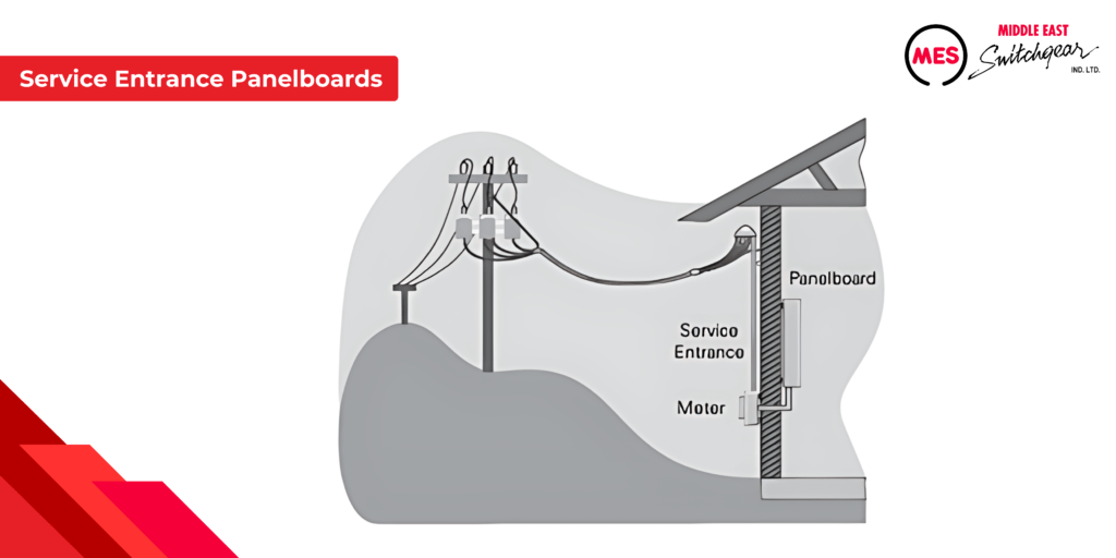
Service Entrance Panelboards
Panel boards are sometimes employed as service entrance equipment for buildings, positioned near the point where electrical power enters. This equipment facilitates the connection of incoming power and provides essential control and cutoff functions.
According to NEC® Article 408, panel boards used in this capacity must meet specific approval and labeling requirements. MES offers panel boards that are factory-labeled as compliant for service entrance applications when all NEC® requirements are fulfilled.
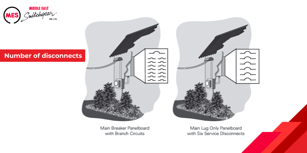
Maximum Number of Disconnects
Panel boards are sometimes employed as service entrance equipment for buildings, positioned near the point where electrical power enters. This equipment facilitates the connection of incoming power and provides essential control and cutoff functions.
According to NEC® Article 408, panel boards used in this capacity must meet specific approval and labeling requirements. MES offers panel boards that are factory-labeled as compliant for service entrance applications when all NEC® requirements are fulfilled.
In the example on the right, a main lug-only panelboard is equipped with up to six circuit breakers to disconnect power to all equipment being supplied by the service. Regardless of which of these examples is used, each circuit breaker must be clearly labeled to show the load it supplies.
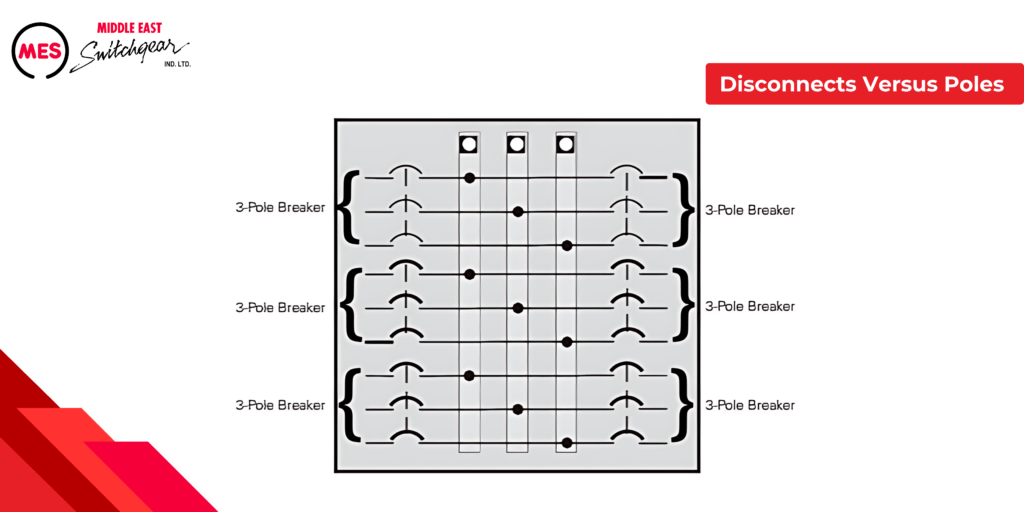
Disconnects Versus Poles
It’s crucial to understand that the ‘six disconnect rule’ pertains to the number of disconnect devices, not the number of poles. For instance, consider the main lug-only panel board illustrated below, which features 18 poles but only six circuit breakers. Here, three poles are mechanically linked to function as a single disconnect device. This configuration allows the service to be disconnected with no more than six operations by hand, thereby complying with the six disconnect rule.
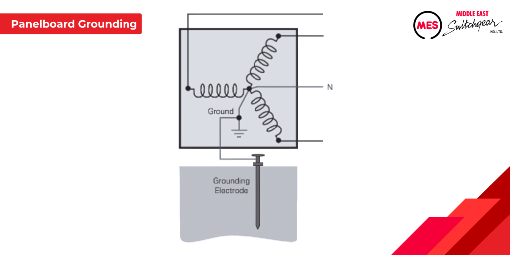
Panelboard Grounding
Grounding is a critical aspect of electrical equipment and requires careful consideration. It involves connecting to the earth or a conductive object that connects to the earth. For example, the accompanying illustration depicts the neutral (N) conductor of a wye-connected transformer grounded. This intentional grounding helps limit voltage differences within a system, ensuring the safety of personnel and protecting equipment and facilities. NEC® Article 250 outlines comprehensive grounding and bonding requirements for electrical installations.
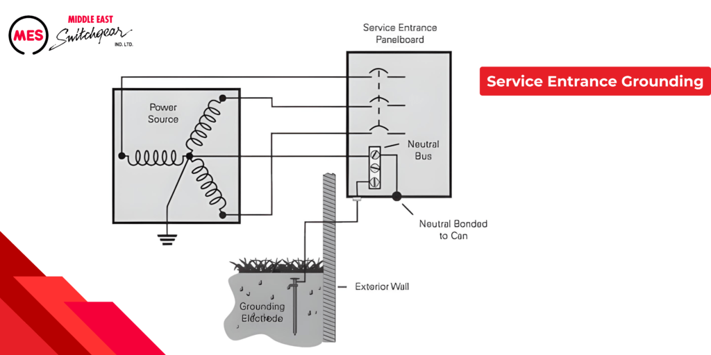
Service Entrance Grounding
In panelboard systems, the neutral conductor plays a crucial role in electrical grounding practices. It is essential to ground the neutral conductor solely at the service entrance and not at any downstream equipment. This grounding process involves connecting a conductor from the neutral (known as the grounded conductor) to a grounding electrode at the service equipment, ensuring safety and proper functionality.
Furthermore, the neutral conductor and the panelboard enclosure are bonded together at the service entrance. This bonding procedure establishes a secure connection between the enclosure and the ground through a grounding electrode connector. This connection, known as bonding, forms a dependable low-resistance pathway for electrical currents, safeguarding against potential hazards and ensuring efficient electrical distribution.
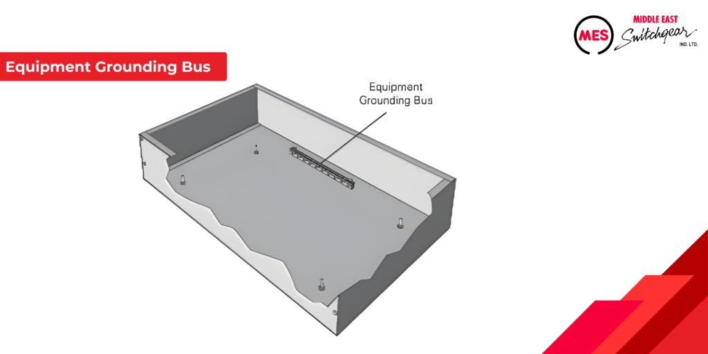
Equipment Grounding Bus
A panelboard may also need an equipment grounding bus, which is uninsulated and mounted directly inside the panelboard’s can. All feeder and branch circuit equipment connected to this bus share the same potential as the panelboard. MES panelboards are equipped with this grounding bus.
Grounding Panelboards Downstream
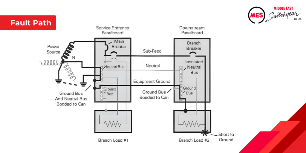
The neutral conductor is grounded solely at the service entrance. In a downstream panel, illustrated below, the neutral is separated from ground and linked to the neutral bus in the service entrance panel. Furthermore, the enclosure of the downstream panel connects to ground via a grounding conductor, which is attached to the ground bus in the service entrance panel.
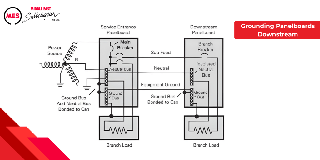
In this example, Load #2 has created a short circuit to its metal enclosure. The fault current returns to the power source along the indicated path. With a well-coordinated system, the branch circuit breaker in the downstream panelboard will trip, disconnecting the load from the power source and preventing further damage.
Ground Fault Protection
A ground fault occurs when electrical current unintentionally flows to the ground, posing risks to both equipment and safety. To prevent damage and enhance safety, ground fault protection is mandatory in certain scenarios.
For example, NEC® Article 230.95 mandates ground fault protection for service disconnects rated 1000 amps or more on solidly grounded wye services with voltages exceeding 150 volts-to-ground but not exceeding 600 volts phase-to-phase.
Ground fault protection equipment must trip the circuit when the fault current reaches 30 milliamps. In contrast, ground fault circuit interrupters (GFCIs) for life safety must trip at 5 milliamps (plus or minus 1 milliamp). When incorporating ground fault protection into a panelboard, it is typically achieved using circuit breakers equipped with ground fault protection.
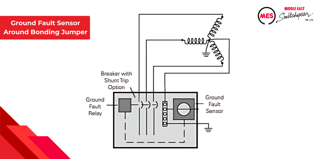
Ground Fault Sensor Around Bonding Jumper
Ground fault protectors operate using a sensor placed around the insulated neutral bonding jumper. When an unbalanced current from a line-to-ground fault occurs, it causes current to flow through the bonding jumper. Once this current reaches a predetermined level, the shunt trip mechanism activates, opening the circuit breaker and disconnecting the load from the power source.
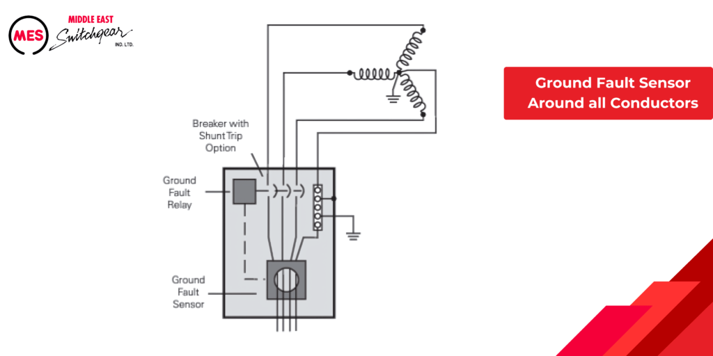
Ground Fault Sensor Around all Conductors
Another method of ground fault protection involves a sensor encircling all the circuit conductors. Under normal conditions, the sum of currents in all conductors is zero. However, a ground fault creates an imbalance in these currents. When this imbalance reaches a specific threshold, the shunt trip mechanism activates, opening the circuit breaker and disconnecting the load from the power source.
Panelboard Interrupting Ratings
Interrupting Ratings
When choosing panelboards and overcurrent protection devices, it’s crucial to know both the available fault current for the application and the interrupting rating of the protective devices being considered.
NEC® Article 110.9 mandates that circuit protection equipment must have an interrupting rating that matches the circuit voltage and available fault current. This requirement can be met using either the full rating method or the series rating method.
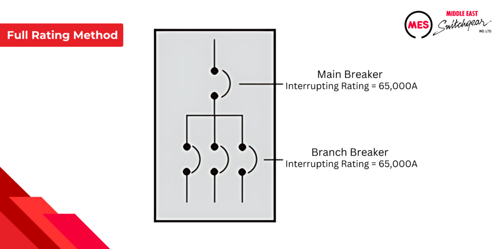
Full Rating Method
The full rating method requires that every circuit protection device have an interrupting rating equal to or greater than the available fault current.
For instance, if a building has 65,000 amperes of fault current available at the service entrance, then each circuit protection device must have an interrupting rating of at least 65,000 A. This requirement is illustrated in the example below, where both the main circuit breaker and each branch breaker are rated for 65,000 A.
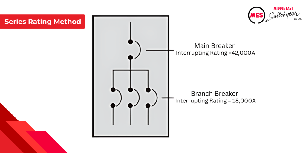
Series Rating Method
An alternative to the full rating method is the series rating method. This approach requires that the main upstream circuit protection device have an interrupting rating equal to or greater than the available fault current of the system. However, downstream circuit protection devices, connected in series, can have lower interrupting ratings.
For example, in a building with 42,000 A of available fault current, the main breaker at the service entrance might have an interrupting rating of 42,000 A, while downstream breakers can be rated lower, such as 18,000 A, as long as they are adequate to handle the current they need to interrupt.
Series Connected Short Circuit Rating
The series rating method is utilized when the selected combination of circuit protection devices has been tested and certified by UL. Each series combination is assigned a series-connected short circuit rating.
MES P Series Panelboards
MES P series panelboards offer a versatile and streamlined approach to power distribution. The P1 model minimizes common installation errors, such as feed direction and choosing between main lug and main breaker configurations. It also simplifies distribution expansion with the addition of feed-through lugs and is well-suited for most lighting panel applications. The P2 model offers high flexibility to meet demanding specifications, while the P3 combines the compact size of a lighting panel with the power capabilities of a distribution panel. The P4 serves as a mid-sized distribution panel, accommodating both fusible and circuit breaker branches and main devices. Lastly, the P5 model is designed for larger distribution systems, providing robust power and flexibility with support for larger fusible and circuit breaker branches and main devices.
● = Standard, – = Not Available
1. Knock-outs available on P1 and P2 5.75″ deep x 20″ wide boxes and P3 7.75″ deep x 24″ wide boxes. 2. Panelboards equipped with MES circuit breakers or power meters can be integrated into the MES Access TM electrical monitoring system.
General Specifications
P series panelboard interiors are designed to support both top and bottom feed configurations. For three-phase panels, branch device poles are consistently arranged with the top pole on the ‘A’ phase, the second pole on the ‘B’ phase, and the third pole on the ‘C’ phase, regardless of the feed direction.
Branch breakers are typically mounted at the top of the panel, with spaces allocated at the bottom, irrespective of the feed direction.
The panel design features bracing up to 200,000 A; however, this does not represent the interrupting rating of the panel, which depends on the specific circuit breaker configuration used.
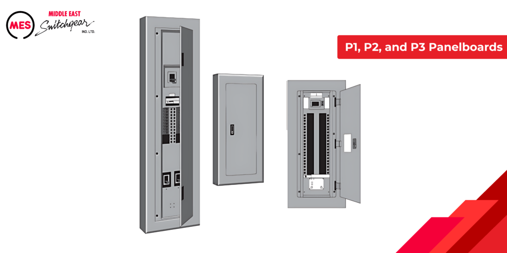
P1, P2 and P3 Panelboards
P1, P2, and P3 panelboards are categorized together in this section due to their similar construction and functionality. These panelboards, like all P series models, are equipped with symmetrical interior mounting studs to prevent issues with upside-down installation. They feature concealed fasteners and hinges, along with a flush door lock for a sleek appearance. Designed for wall mounting, P1, P2, and P3 panelboards come with standard temperature-rated aluminum bussing with tin plating, though alternative bussing options are also available.
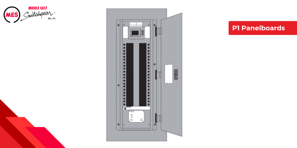
P1 Panelboards
- Versatile Interior Design: The interiors have no fixed top or bottom, allowing for easy conversion from top-feed to bottom-feed by simply inverting the interior. The dead front labeling remains correctly oriented.
- Varied Ratings: Available in ratings from 125 to 400 A for main lug panels and 100 to 400 A for main breaker panels.
- Field-Convertible: Can be converted from main lug to main breaker and vice versa without increasing the enclosure height.
- Feed-Thru Options: Includes feed-thru lugs, a subfeed breaker, or a surge protection device in feed-thru (FT) panel versions.
- Space-Saving Design: Non-feed-thru (NFT) panels reduce panel height by six inches when feed-thru space is not needed.
- Upgradeable Neutral System: The neutral system can be upgraded to 200% capacity in the field.
- Bonding Provisions: Each panel comes with bonding provisions.
- Service Entrance Suitability: Can be used as service entrance equipment, provided NEC® compliance is met.
- Uniform Box Design: 250 V and 480 Y/277 V versions use the same boxes and fronts.
- Circuit Capacity: Accommodates up to 18, 30, 42, 54, or 66 circuits.
- Cost Efficiency: Extended circuit options (54 or 66 circuits) may reduce project costs by eliminating the need for additional panels or larger P2 or P3 panels.
P1 Unassembled Panelboards
Authorized MES unassembled panelboard distributors offer high-quality P1 panelboards that are suitable for use as service entrance equipment. These panelboards come with clear labeling and are designed to ensure trouble-free operation.
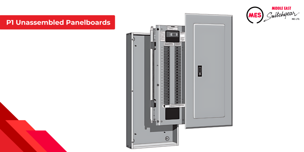
This program enables distributors to offer same-day availability of unassembled P1 panelboards that match MES factory-assembled panels in quality and design. The unassembled P1 panelboards feature several design elements to streamline assembly:
- Symmetrical Box Design: The box can be mounted with either end up, providing installation flexibility.
- Pre-Punched for Customization: The box is pre-punched for optional field-installable door-in-door or hinged-style trims.
- Rotatable Interior: The interior can be rotated to switch from top-feed to bottom-feed configurations.
- Simplified Main Installation: The main breaker and main lug kits are designed for easy installation.
- Efficient Wiring: Branch-neutral connections are located close to the breaker connections, reducing wiring time and minimizing clutter.
- Expandable Options: Space is available to add a sub-feed breaker (up to 250 amps), feed-thru lugs, or a TPS3 surge protection device kit.
- Enhanced Safety: MES standard trim includes hidden hinges and mounting hardware.
- Secure Panel Door: The panel door features a semi-flush lock as a standard feature for added security.
P2 Panelboards
P2 panelboards offer a wide variety of factory-assembled options to meet most lighting panel application requirements. The P2 design also offers the ability to mix breaker frames in unit space up to 250 A to meet many power distribution panel requirements in a much smaller package.
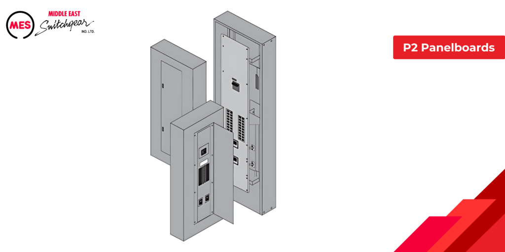
In addition to standard bussing, P2 panelboards offer several bussing options, including temperature-rated copper, 750 A/sq. in. aluminum, or 1000 A/sq. in. copper. Bussing is typically tin-plated, with silver-plated copper available as an option. These bussing options are also applicable to P3, P4, and P5 panelboards.
P2 panels are available in circuit configurations of 18, 30, 42, 54, 66, 78, and 90. Additionally, blank unit spaces can be included to accommodate future expansions or modifications.
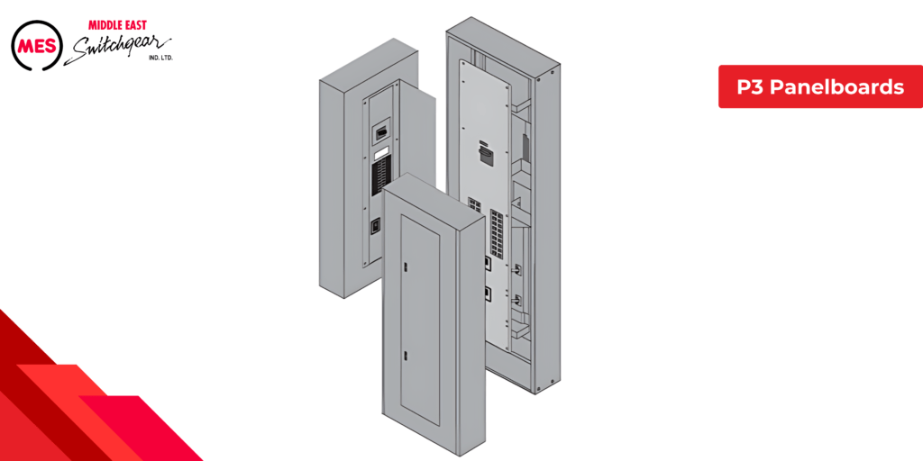
P3 Panelboards
P3 panelboards are compact power distribution panels designed for applications requiring more branch devices or larger capacities than typical lighting panelboards.
They offer a broad range of factory-assembled options and can accommodate mixed breaker frames in unit spaces up to 250 A.
P3 panels are available in enclosure heights of 56, 62, 68, 74, or 80 inches. As with other power distribution panels, P3 panelboards can be configured with blank spaces to facilitate future expansions or modifications.
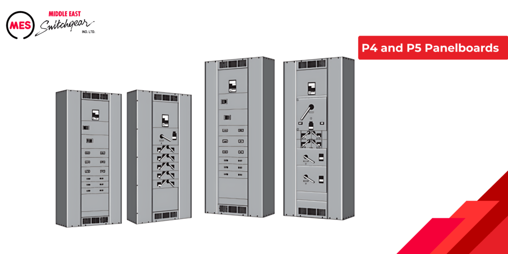
P4 and P5 Panelboards
P4 and P5 power panelboards share a similar design and feature set but differ in their available ratings. P4 panelboards are designed with a medium footprint to handle applications requiring larger branch devices and higher current ratings than those typical of lighting and appliance panelboards. They can accommodate circuit breaker frames up to 800 A and fusible switches up to 200 A.
P5 panelboards have the largest footprint in the P series, supporting even higher-rated main and branch devices, including circuit breaker frames and fusible switches up to 1200 A.
P Series Panelboards Catalog Numbers
The P series panelboard catalog number description offers a summary of the panelboard’s specifications.
Each catalog number describes the panelboard and consists of nine parts, as illustrated in the example below.
Part 1
Part 1 identifies the type of panel, P1, P2, P3, P4, or P5. The sample panelboard catalog number shown is a P1 panelboard.
Part 2
Part 2 identifies the voltage and system. The following table shows voltage and system configurations available.
The panelboard in this example is configured for a 208Y/120V, 3Ø4W power system as shown in the following illustration.
Part 3
Part 3 of the catalog number specifies the number of circuits for P1 and P2 panelboards. For P3, P4, or P5 panelboards, this part denotes the enclosure height in inches. In the example provided, the panelboard is a P1 model with 42 circuits.
Part 4
Part 4 of the catalog number specifies the type of main device in the panelboard. This part identifies whether the panelboard has a main breaker (with a 2-digit code specific to each circuit breaker type), main lug (ML), or main switch (MS). In the given example, ‘FX’ denotes that the panelboard is equipped with an FXD6 main breaker.
Part 5
Part 5 indicates the panelboard current rating. In this example, the panelboard is rated for 250 amps.
Part 6
Part 6 of the catalog number specifies the bus material used in the panelboard. The available bus materials are detailed in the table below. In this example, ‘A’ indicates that the panelboard is equipped with standard temperature-rated aluminum bus bars with tin plating.
Part 7
Part 7 indicates whether feed location is from the top (T) or bottom (B). In this example, the panelboard is top fed.
Part 8
Part 8 indicates whether the panelboard is surface mounted (S) or flush mounted (F). In this example, the panelboard is surface mounted.
Part 9
Part 9 is the sub feed space indicator for P1 panels only. T = subfeed space included. N = no subfeed space.
Ordering Information
To minimize errors when ordering panelboards, ensure you have the correct answers to the following questions:
- What is the power system? Specify the voltage, phases, and number of wires.
- What is the required interrupting rating for the panel?
- Which NEMA-type enclosure is needed?
- How many circuits are required for a P1 or P2 panel, or what will the enclosure height be for a P3, P4, or P5 panel?
- Does the panelboard need to be suitable for service entrance? Panels with a Suitable for Use on Service Entrance (SUSE) label are available if NEC® requirements are met.
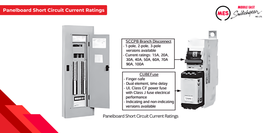
Quick-Spec Coordination Panelboards
ES Quick-Spec Coordination Panelboards offer fusible solutions that simplify and economize the process of selectively coordinating a fused electrical distribution system. These panelboards are specifically designed to meet NEC® selective coordination requirements, which is crucial for many businesses. Selective coordination helps prevent unnecessary outages that could negatively impact business operations and productivity. MES coordination panels are ideal for emergency systems, legally required standby systems, healthcare essential electrical systems, and critical operation power systems.
- Voltage Ratings: 600VAC, 125VDC
- Current Ratings: 30A, 60A, 100A, 200A, 225A, 400A
- Main Options: Main lug only, fused main disconnect, non-fused main disconnect
- Branch Circuit Positions: 18, 30, 42
- Neutral Options: Unbonded and bonded (200A, 400A, 800A)
- Ground Options: Isolated and non-isolated
- Enclosures: NEMA 1 and NEMA 3R
Additional Types of Panels and Cabinets
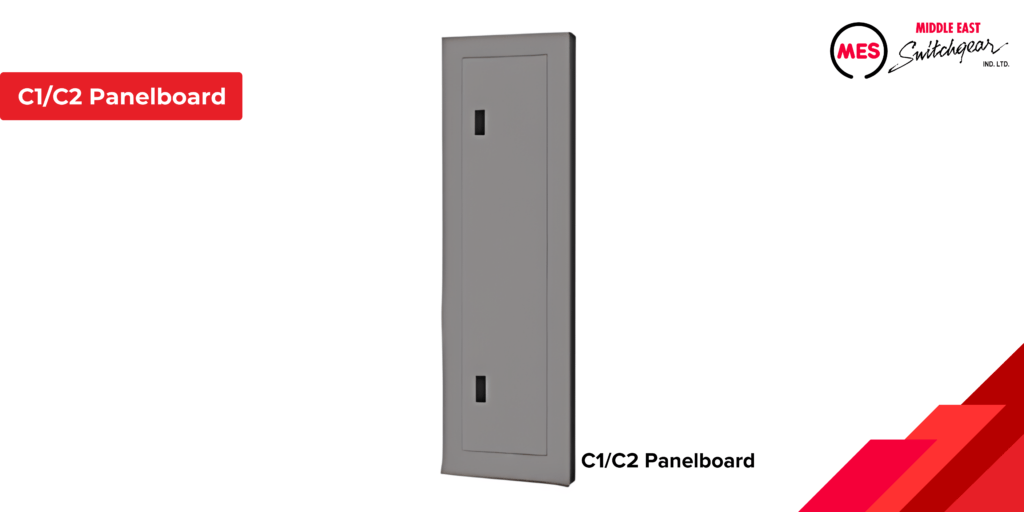
In addition to the P series and coordination panelboards covered in this course, MES also provides C1 and C2 column-type panelboards, lighting control panels, and telephone and equipment cabinets.
The C1 and C2 panelboards are designed with a narrow width, ideal for column mounting. The C1 panelboards support a maximum supply voltage of 250 VAC, while the C2 panelboards are designed for a maximum supply voltage of 480Y/277 VAC. Both C1 and C2 panels accommodate up to 250 A mains and can be configured with either a main breaker or main lug only.
MES telephone and equipment cabinets have a depth of 5.75 inches, and come in widths of 20 or 24 inches, with heights ranging from 23 to 59 inches. These cabinets are equipped with MES FAS latch fronts, concealed hinges, and fastening screws.
Accessories
Accessories enhance the performance of a panelboard or tailor it to meet specific application needs. MES offers a range of accessories for their panelboards. For instance, the shunt trip accessory described on this page is one example of a circuit breaker accessory.
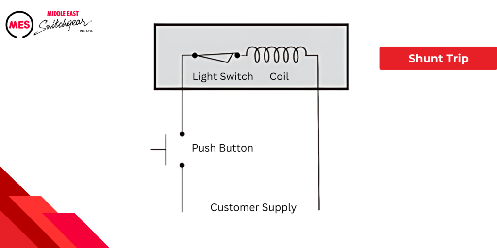
Shunt Trip
Certain accessories modify circuit breakers to meet specific needs. For instance, tripping a breaker from a remote location may be necessary for safety applications, such as activating a ‘panic button’ to de-energize machinery quickly. This can be achieved using a circuit breaker equipped with a shunt trip accessory.
The shunt trip can be installed on either the main breaker, which will cut off power to the entire panelboard, or on a branch breaker. The device consists of a coil connected in series with a limit switch. When the circuit breaker’s contacts are closed, the limit switch is also closed. Pressing a customer-supplied push button energizes the shunt trip coil, which disengages the breaker’s mechanical latch and trips the breaker, opening its contacts. Once the contacts open, the limit switch disconnects, cutting power to the shunt trip coil. Note that the breaker must be manually reset after tripping.
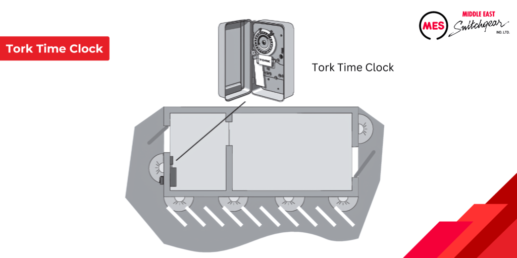
Time Clocks
Tork, Sangamo, and Paragon time clocks are available as external accessories for P1 panelboards and can be mounted internally in P2, P3, P4, or P5 panelboards. These time clocks come in various configurations, including 1 or 2-pole, single or double-throw, and 3-pole, single throw, with a maximum rating of 277 volts. They can be used to control branch circuits or an entire panelboard by switching them on and off at scheduled times. For example, a time clock can be used to automate the operation of outside lights for a small commercial building, as illustrated below.
Remote Control Switches
When an application requires remote control of loads, an ASCO 911 or 920 mechanically-held remote control switch or MES LEN electrically-held contactor can be mounted in a separate cabinet as a main disconnect.
TPS3 Transient Protection Systems
Electrical devices and systems are often vulnerable to damage from electrical surges caused by lightning or other equipment-induced disturbances. Any component between the surge source and the ground can be at risk. Thus, surge protection is essential to ensure the reliability and safety of electrical systems. The best approach to surge protection is to install hard-wired surge protection devices (SPDs) at key entry points to prevent surges from entering the system.
MES TPS3 Transient Protection Systems are designed according to the UL 1449 3rd edition standard for hard-wired SPDs, offering both superior safety and high performance. The TPS3 family of commercial SPDs provides consistent performance parameters and comes in two configurations: integral SPDs (built directly into our distribution equipment) and external or wall-mounted SPDs.
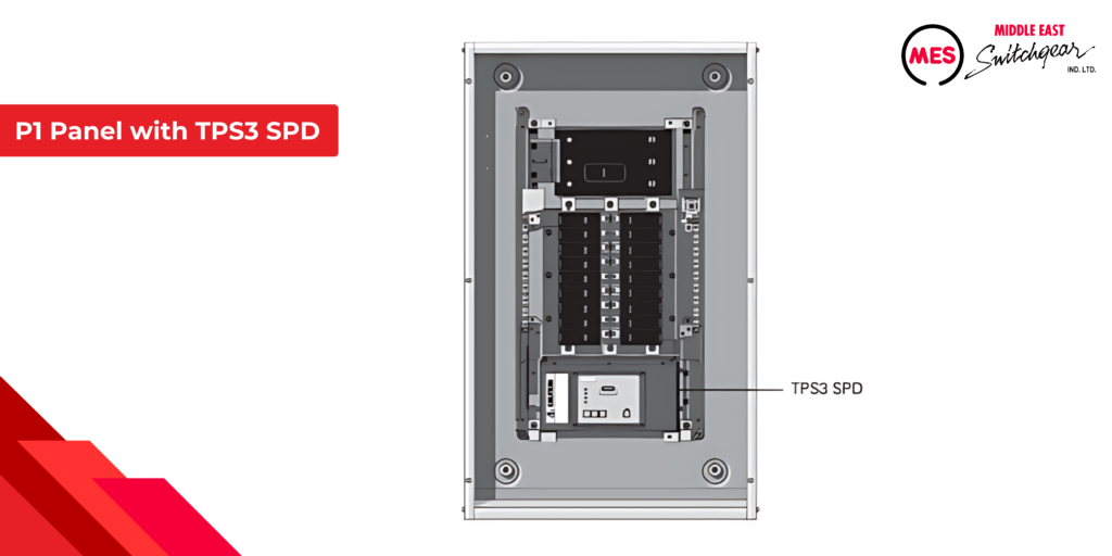
TPS3 options are available for MES panelboards and other distribution equipment. For example, an integral TPS3 SPD option for a P1 panelboard bolt directly to the panelboard bus bars. This setup includes LEDs for operational status and voltage monitoring, an audible alarm, and a test button. Additional features may include a surge counter and a remote monitoring device for enhanced oversight.”
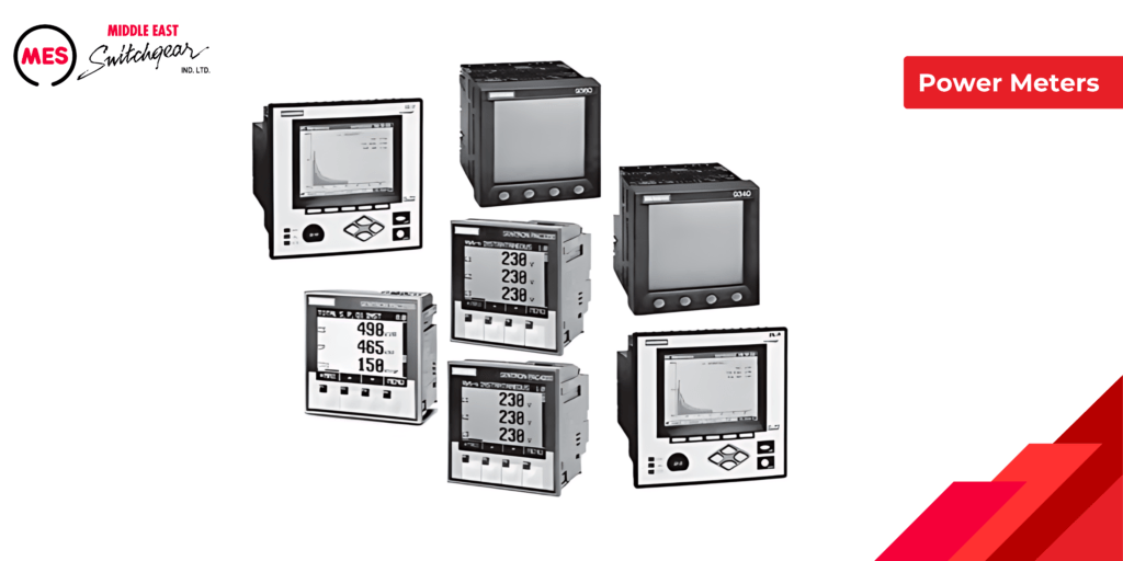
Power Meters
In today’s intricate business environment, power monitoring systems often require meters that range from basic energy and power meters to advanced power quality meters capable of gathering data from multiple sources. While smaller systems may only need low-cost, stand-alone meters, the increasing demand for comprehensive energy management and system performance monitoring necessitates communication with various devices.
MES provides a complete range of metering solutions to meet virtually any power monitoring requirement. The MES SENTRON PAC series of meters can be installed in P2, P3, P4, and P5 panelboards, offering versatile options for different applications. The MES meters are also compatible with P4 and P5 panelboards, providing advanced metering capabilities for more demanding power monitoring needs.
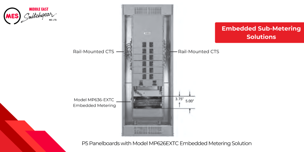
Embedded Sub-Metering Solutions
In commercial building designs where tenant square footage is at a premium, space for electrical metering is often severely limited. Additionally, rising contractor labor costs for installing sub-metering systems add to the challenge. MES addresses these issues with cost-effective, integrated solutions for embedded metering and monitoring.
MES offers a comprehensive embedded metering system that is factory-installed in MES switchboards and P series panelboards. This solution, combined with local or remote sub-billing software, delivers a complete sub-metering system. Compared to traditional wall-mounted socket metering installations, MES’ embedded metering solutions offer significant savings in space, installation costs, and data collection.
A typical embedded metering setup includes:
- Rail-mounted CTs (current transformers) that connect to a central metering unit mounted within the unit space.
- A 15 amp, 3-pole breaker to power the units and provide a voltage reference.
- Built-in communications for seamless data integration.